Aerosol system

a technology of aerosol and actuator, which is applied in the direction of brushes, containers, liquid dispensing, etc., can solve the problems of unfavorable ejection, unfavorable ejection, and the design of reusing the inner container is difficult to achieve, and achieves a high degree of safety regarding ejection. , the effect of convenient and comfortable us

Active Publication Date: 2009-01-22
KAO GERMANY GMBH
View PDF18 Cites 6 Cited by
  • Summary
  • Abstract
  • Description
  • Claims
  • Application Information

AI Technical Summary

Benefits of technology

[0008]It is, therefore, an object of the present invention to provide an aerosol system containing two or more aerosol containers which is easy and comfortable to use and provides at the same time a high degree of safety regarding ejection of the desired fluid.

Problems solved by technology

These container systems have the disadvantage that a design of reusing the inner container is hard to accomplish.
Such a design does not exclude accidentally operating the wrong and / or both actuators which may have undesired consequences, depending on the field of application.
Further, additional components in the form of a second actuator could increase costs and weight.
In such applications, it is hardly avoidable that product fluids adhere to parts of the head portion when being ejected and thereby contaminating the channel system and other components.
This might reduce the performance of the aerosol system as well as undesirably pollute other product fluids having the same flow path.

Method used


Image

  • Aerosol system
  • Aerosol system
  • Aerosol system

Examples


second embodiment

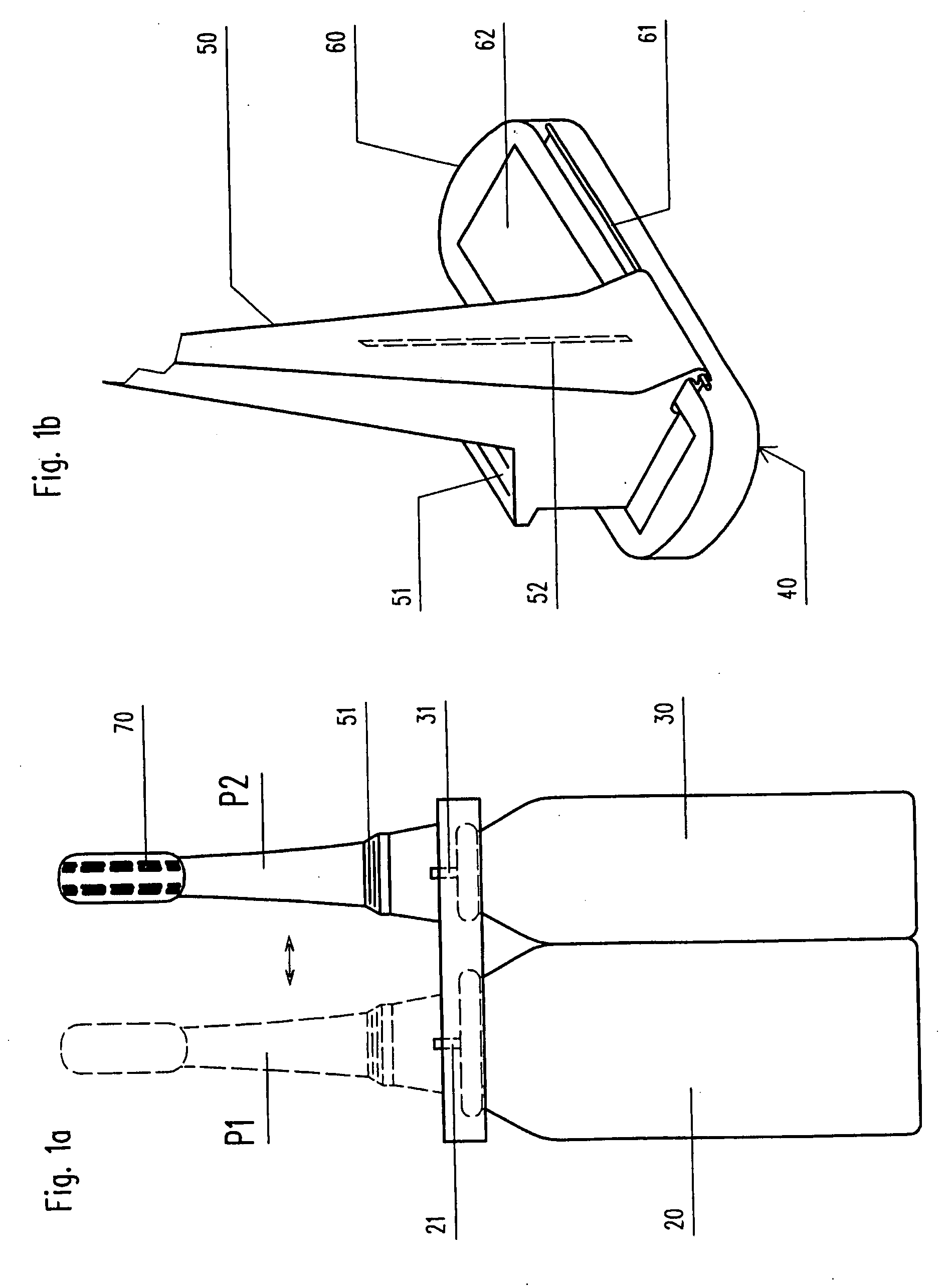
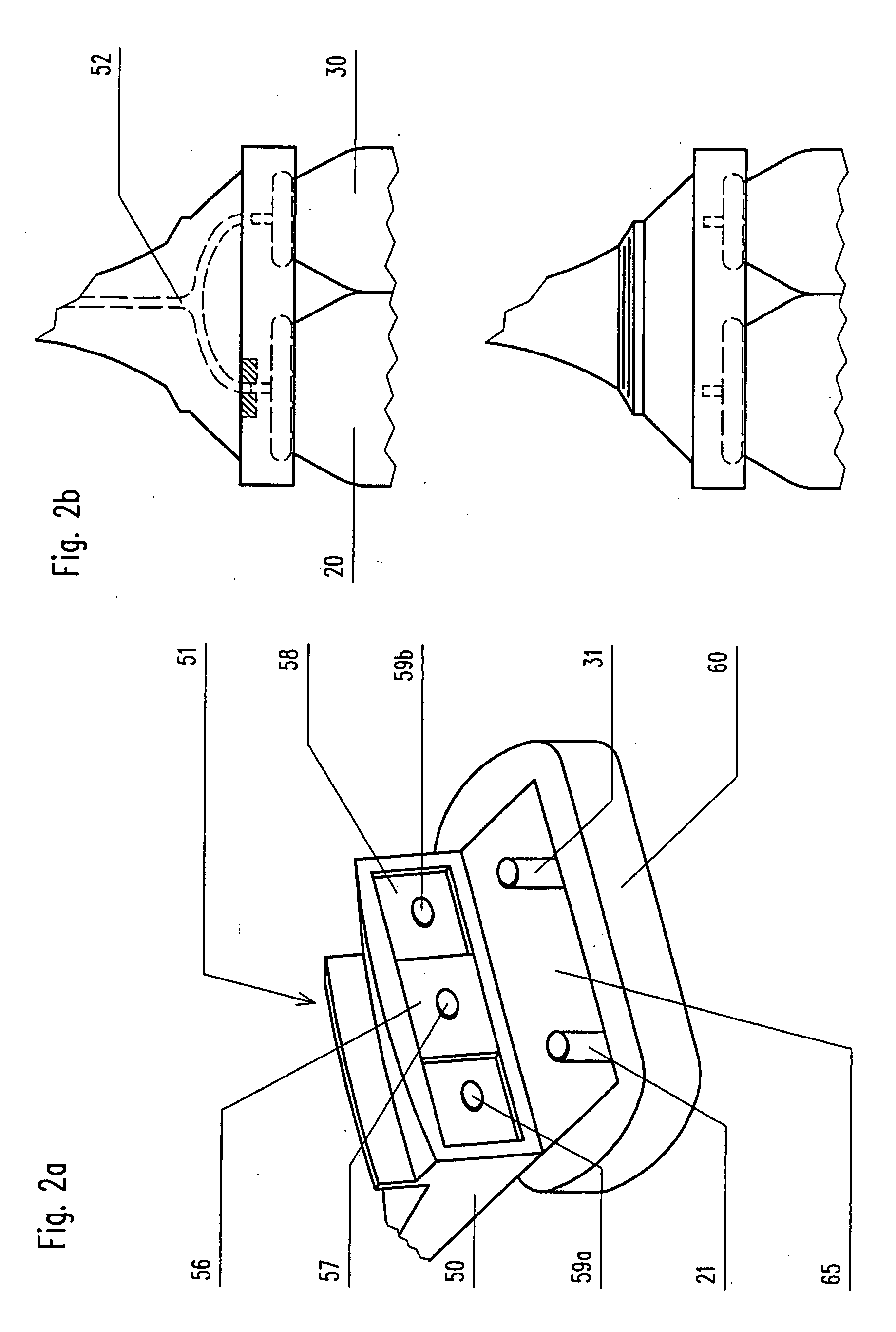
[0033]A second embodiment according to FIGS. 2a and 2b is described below. The head portion 40 in FIG. 2a contains a lower part 60 and an upper part 50. Similar to the previous embodiment, the upper part 50 has an actuator 51 serving for both aerosol containers 20, 30. The upper part 50 is tiltable connected to the lower part 60 which is fixedly attached to the aerosol containers 20, 30. The articulation means 65 allows for opening the head portion 40 by tilting the upper part 50 with respect to the lower part 60. It is advisable to provide a means for securing the head portion 40 in a closed position (not shown in the Figures).

[0034]The upper part 50 of the head portion 40 has a slider 56 disposed within an extended rectangular upper opening 58 allowing the slider 56 to be moved along a predetermined path. The slider contains a hole 57 which is part of a flow path between a valve portion 21, 31 and the exhaust opening 53.

[0035]In contrast to the previous embodiment the operation mo...

third embodiment

[0039]FIGS. 3a and 3b show the present invention using a twister instead of a slider for changing the configuration of the aerosol system 10. Many features and elements are similar to those of the previous embodiment and carry the same reference signs.

[0040]The communication between a valve portion 21, 31 of one of the containers 20, 30 and the exhaust opening 53 is achieved via a twister 56a. The twister contains a hole 57a and a cavity 58. Similar to the aforementioned slider, the hole 57a provides communication between the channel entrance of the upper part 50 of the head portion 40 and a valve portion 21, 31 of an aerosol container 20, 30.

[0041]Again, the upper part 50 of the head portion 40 includes two openings which are the entrances of respective channels. Both channels are combined within the upper part 50 of the head portion 40 to form a single output channel ending at an exhaust opening 53 (not shown in the figures). The twister is rotatably mounted to the upper part 50 o...


PUM


Abstract

Aerosol System comprising at least two aerosol containers for separately keeping different substances, wherein each aerosol container has a valve portion; and a head portion containing a channel system and an exhaust opening, where the channel system provides communication between at least one of the valve portions and the exhaust opening; characterized in that the head portion or parts of the head portion are movable in respect to at least one aerosol container, such that the channel system can take different configurations.

Description

TECHNICAL FIELD[0001]The present invention relates to an aerosol system of two or more aerosol containers including a cleaning function.BACKGROUND ART[0002]Aerosol systems, comprising two or more aerosol containers, are well known and designed to allow two or more fluid components to be mixed when operating the system. These systems are, for example, known as two-component systems which are used for colours or hair tinting lotions or other fluids which need to be separated, until ejection, for avoiding an undesired mixture or a precipitated reaction of the components.[0003]For this purpose, there is known a two-component system including two containers which are interleaved, wherein the outer container contains a valve portion operating the valve of the second container and at the same time ejecting the mixed fluid. These container systems have the disadvantage that a design of reusing the inner container is hard to accomplish.[0004]DE 23 25 512 discloses an aerosol system containin...

Claims


Application Information

Patent Timeline
Patent Type & Authority Applications(United States)
IPC IPC(8): B65D83/14
CPCB65D83/68B65D83/22B65D83/20
Inventor KRAUS, SEBASTIAN
Owner KAO GERMANY GMBH
Why Eureka
Try Eureka