Control Device, RFID Tag Reading System and RFID Tag Reader

a technology of rfid tag and reading system, which is applied in the direction of near-field systems using receivers, instruments, burglar alarm mechanical actuation, etc., can solve the problem that the rfid tag reader cannot read the rfid tag properly, and achieve the effect of reducing possibility, avoiding communication congestion and collision, and improving the reading efficiency of the rfid tag

Active Publication Date: 2009-01-22
UNIVERSAL ENTERTAINMENT CORP
View PDF3 Cites 47 Cited by
  • Summary
  • Abstract
  • Description
  • Claims
  • Application Information

AI Technical Summary

Benefits of technology

[0013]This control device enables the second RFID tag reader to use the second unit radio channel prior to the first unit radio channel. Therefore, reading by the first RFID tag reader is less likely blocked by the second RFID tag reader, and also, reading by the second RFID tag reader is less likely blocked by the first RFID tag reader. As a result, reading efficiency of the RFID tag can be improved.
[0036]According to the present invention, communication congestion and collision can be avoided by effectively assigning a unit radio channel for transmission and reception to RFID tag readers using the same unit radio channel group.

Problems solved by technology

In both the high-output 950 MHz band passive tag system and the low-output 950 MHz band passive tag system, the RFID tag reader can be unable to read the RFID tag properly in the presence of another RFID tag reader in the vicinity thereof, due to: interference between two RFID readers, or between an RFID reader and an RFID tag not designated therefor; and communication congestion and collision due to interference between emitted radiowaves or channel interference in the same frequency band.

Method used


Image

  • Control Device, RFID Tag Reading System and RFID Tag Reader
  • Control Device, RFID Tag Reading System and RFID Tag Reader
  • Control Device, RFID Tag Reading System and RFID Tag Reader

Examples


Embodiment Construction

[0065]Hereinafter, an embodiment of the present invention is explained with reference to the drawings. First, a basic configuration of an RFID tag reading system according to the present embodiment is described below.

1. RFID Tag Reading System

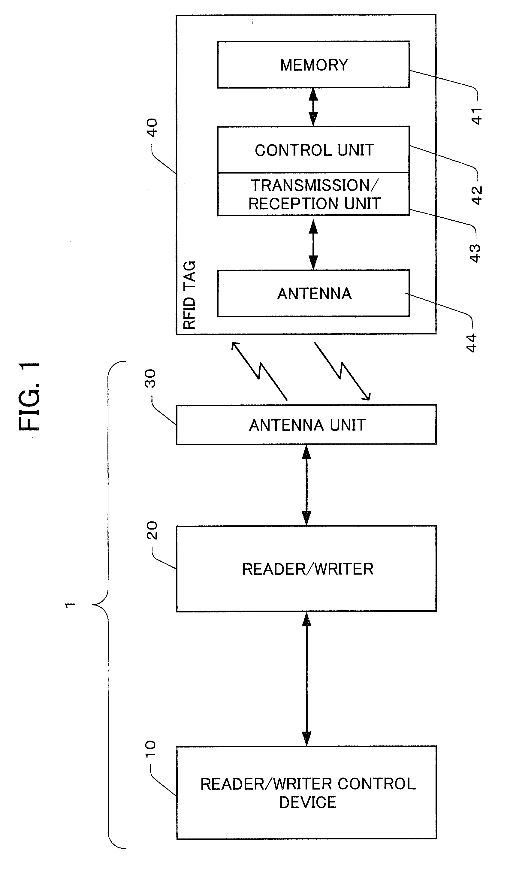
[0066]FIG. 1 is a functional block diagram illustrating an example of a basic configuration of an RFID tag reading system according to the present embodiment of the present invention. It should be noted that a high-output RFID tag reading system and a low-output RFID tag reading system are different in radio transmission output for reading and the amount of unit radio channels available; however, the basic configuration is the same. Hereinafter, a high-output RFID tag reading system and a low-output RFID tag reading system are referred to as RFID tag reading system 1. A configuration example of the RFID tag reading system 1 is described below.

[0067]The RFID tag reading system 1 is composed of: a reader / writer control device 10; a reader / writer ...


PUM


Abstract

It is an object of the present invention to avoid communication congestion and collision by effectively assigning a unit radio channel for transmission and reception to RFID tag readers using the same unit radio channel group. Herein disclosed is an RFID tag reading system for reading an RFID tag using a reader / writer used in a low-output RFID tag reading system capable of using channels 1 to 9 available for a reader / writer used in a high-output RFID reading system and channels 10 to 14 not available for a reader / writer used in the high-output RFID tag reading system. The RFID tag reading system receives an RSSI indicative of a received radiowave strength on each of unit radio channels measured by the reader / writers, and assigns channels 1 to 14 preferentially to channels 1 to 9 based on the RSSI.

Description

[0001]This application is based on and claims the benefit of priority from Japanese Patent Application No. 2007-027340, filed on 6 Feb. 2007, the content of which is incorporated herein by reference.BACKGROUND OF THE INVENTION[0002]1. Field of the Invention[0003]The present invention relates to a control device, an RFID tag reading system and an RFID tag reader. More specifically, the present invention relates to a control device and an RFID tag reading system for a reader (for example, a reader / writer) having a reading function for reading so-called RFID tags (radio frequency identification tag, also called as electronic tag), and such an RFID tag reader.[0004]2. Related Art[0005]Among so-called RFID tags, a 950 MHz band passive tag has an available frequency band assigned, which is from 950 MHz to 956 MHz. In this available frequency band, a band actually available in Japan is from 952 MHz to 955 MHz except a guard band. The band can be divided into up to 14 a unit radio channels ...

Claims


Application Information

Patent Timeline
Patent Type & Authority Applications(United States)
IPC IPC(8): H04Q5/22G08B13/14
CPCH04B5/0031H04B5/02H04B5/0056
Inventor NONAKA, NOBUYUKI
Owner UNIVERSAL ENTERTAINMENT CORP
Why Eureka
Try Eureka