Custom video composites for surveillance applications

a video composite and surveillance application technology, applied in the field of security systems, can solve the problems of system and salvo operation falling short in other important monitoring tasks and operations, application tools known salvo or matrix view monitoring systems do not provide a single view port, so as to reduce/optimize network traffic and system or network bandwidth requirements

Active Publication Date: 2009-01-22
HONEYWELL INT INC
View PDF10 Cites 89 Cited by
  • Summary
  • Abstract
  • Description
  • Claims
  • Application Information

AI Technical Summary

Benefits of technology

[0015]The invention may include that any of the video sources shown therein may be mega-pixel video sources, such that when a composite view is defined (composite view definition), any mega-pixel source providing an ROI will send only the video data comprising the ROI, not the entire streaming FOV, and that the processor that renders the reconstructed composite FOV operates only on the video data of the streaming ROI. Such operation is particularly desirable in that the bandwidth required to transmit an ROI may be much smaller than that required to transmit all of the data comprising the FOV with respect to one mega-pixel video source, or like device (one ROI comprising the composite FOV). Of course where multiple mega-pixel video sources (or like devices) are supplying video data comprising ROIs (in lieu of the entire FOV), the system or network bandwidth requirements are further reduced, thereby reducing / optimizing the network traffic.

Problems solved by technology

So while conventional salvo or matrix view techniques for monitoring multiple FOVs may provide for viewing the video acquired at any one of the monitored FOVs, such systems and salvo operation falls short in other important monitoring tasks and operations.
Known salvo or matrix view monitoring systems and application tools do not provide a single view port to monitor multiple regions of interests (ROIs) in a single contained view or viewing port.

Method used


Image

  • Custom video composites for surveillance applications
  • Custom video composites for surveillance applications
  • Custom video composites for surveillance applications

Examples


Embodiment Construction

[0021]The inventive video surveillance system, method and application program tool of the invention are described herein with the accompanying drawings in order to convey the broad concepts of the invention. The drawings figures and textual descriptions however, are meant for illustrative purposes only, and are not meant to limit the scope and spirit of the invention, or in any way limit the scope of the invention as claimed.

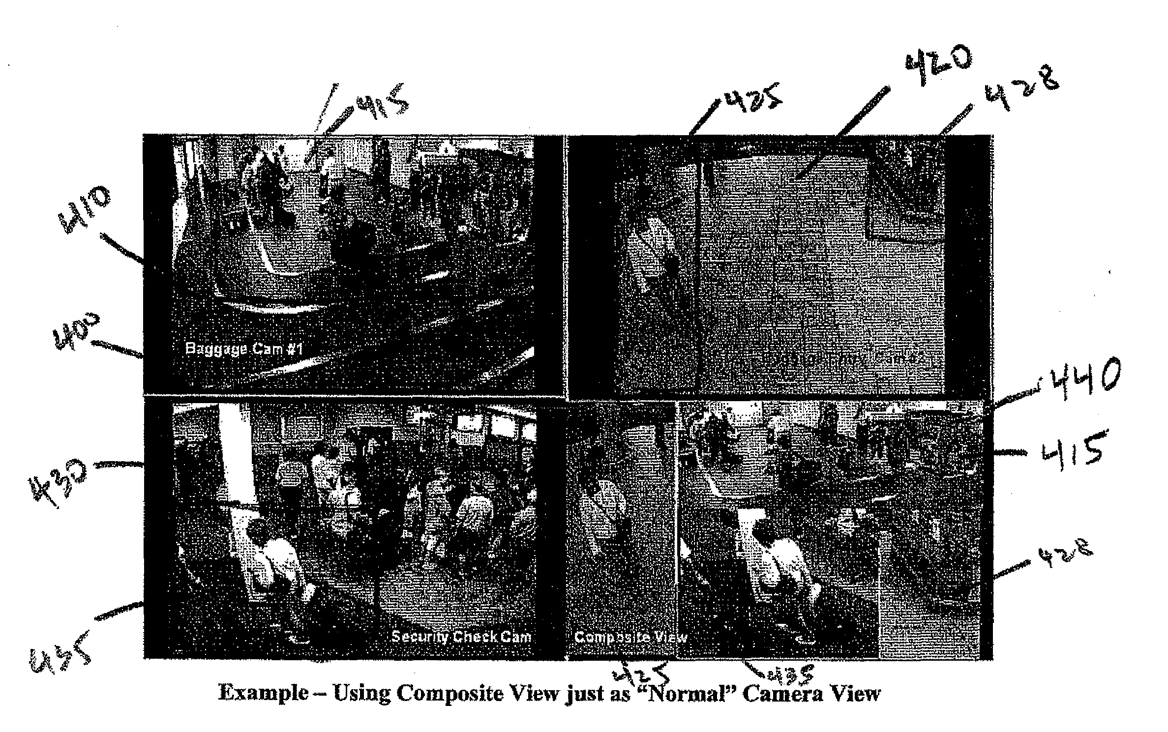
[0022]In one embodiment, the present invention includes a video surveillance system that allows an operator or end user to generate and monitor a composite field of view (FOV) comprising multiple sub-views, or regions of interest (ROIs). The ROIs are identified and selected by an end-user within any FOV, which FOVs comprise the streaming video acquired by video sources comprising the video surveillance system.

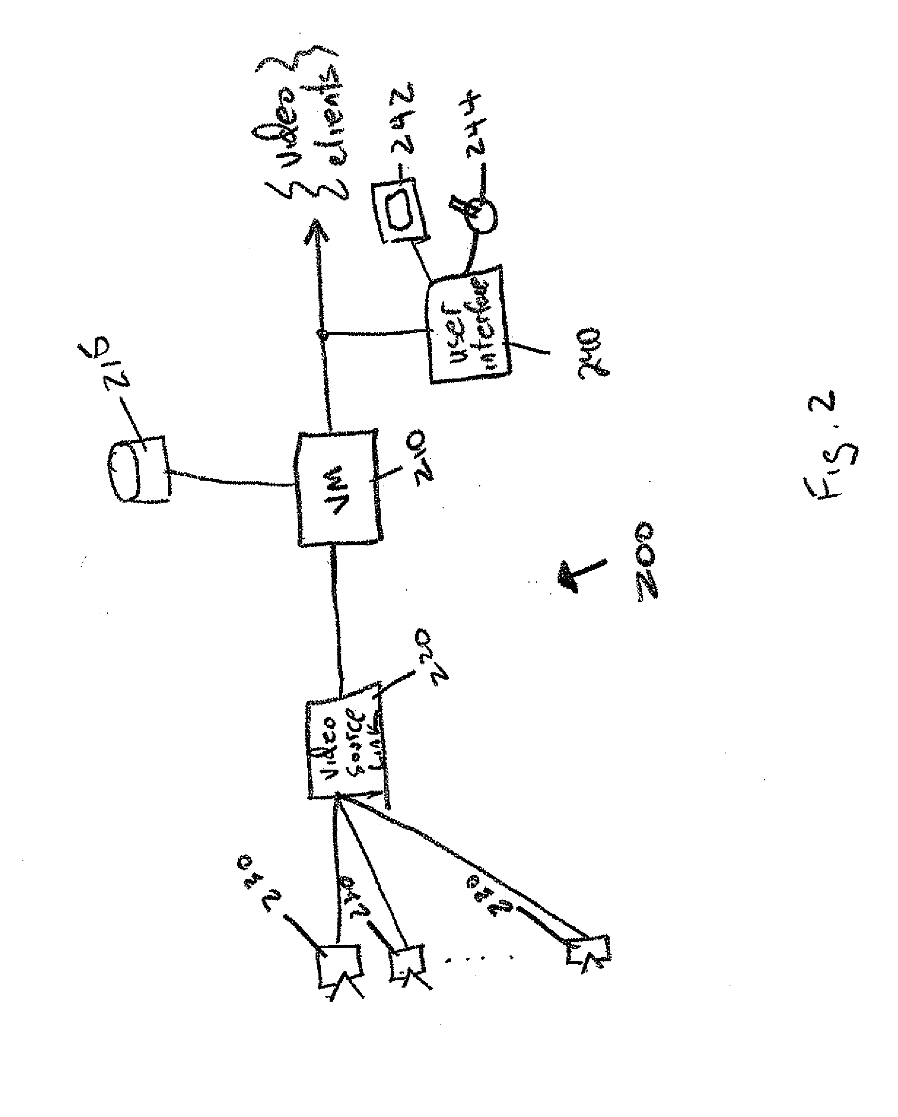
[0023]More particularly, the inventive video surveillance system comprises a plurality of video sources, where each video source is arranged to monitor and...


PUM


Abstract

A video surveillance system includes a plurality of video sources, where each video source is arranged to monitor and acquire video surveillance data within a field of view (FOV), a video manager connected to each of the plurality of video sources to control the video sources and to process video surveillance data acquired therefrom and a user interface connected to the video manager that allows an end-user to observe the FOVs from each of the plurality of video sources, and identify a region of interest (ROI) within particular FOVs to dynamically render a composite FOV comprising the ROIs from the particular FOVs. Where a video source includes enhanced abilities, such as a mega-pixel camera or video source, the enhanced video source may forward, instead of video data for the entire FOV, only that video dated from the selected ROI to realize reduced network traffic for more optimal video surveillance applications.

Description

BACKGROUND OF THE INVENTION[0001]The present invention relates to security systems, and more particularly relates to custom video composites and use within video surveillance systems, automated methods and software application tools for video surveillance.[0002]Video surveillance systems are known for use in a variety of applications for monitoring objects within an environment, e.g., a piece of baggage in an airport or a casino employee within a gambling establishment. Video surveillance has long been employed in the aviation industry to monitor the presence of individuals at key locations within an airport, such as at security gates, baggage area, parking garages, etc. Analog closed circuit television (CCTV) and more recently available digital, network-based video surveillance systems are employed to monitor and / or track individuals and objects, vehicles entering or leaving a building facility or security gate (entry / exit), individuals present within, entering / exiting a store, cas...

Claims


Application Information

Patent Timeline
Patent Type & Authority Applications(United States)
IPC IPC(8): H04N7/18
CPCH04N7/181
Inventor SALGAR, MAYURDRIVE, MARINESUBBIAN, DEEPAKUMARJAYAPPA, MAHESH N.
Owner HONEYWELL INT INC
Why Eureka
Try Eureka