Wireless transceiver and microphone based communications system

Inactive Publication Date: 2009-01-22
JTS PROFESSIONAL
View PDF8 Cites 7 Cited by
  • Summary
  • Abstract
  • Description
  • Claims
  • Application Information

AI Technical Summary

Problems solved by technology

One drawback is that wires may get tangled.
This inevitably will increase operating cost greatly.

Method used


Image

  • Wireless transceiver and microphone based communications system
  • Wireless transceiver and microphone based communications system
  • Wireless transceiver and microphone based communications system

Examples


Embodiment Construction

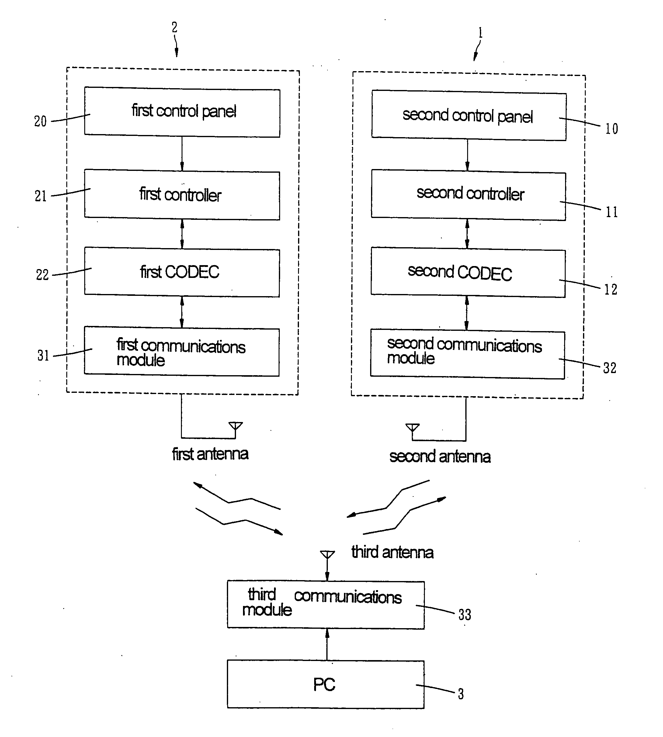
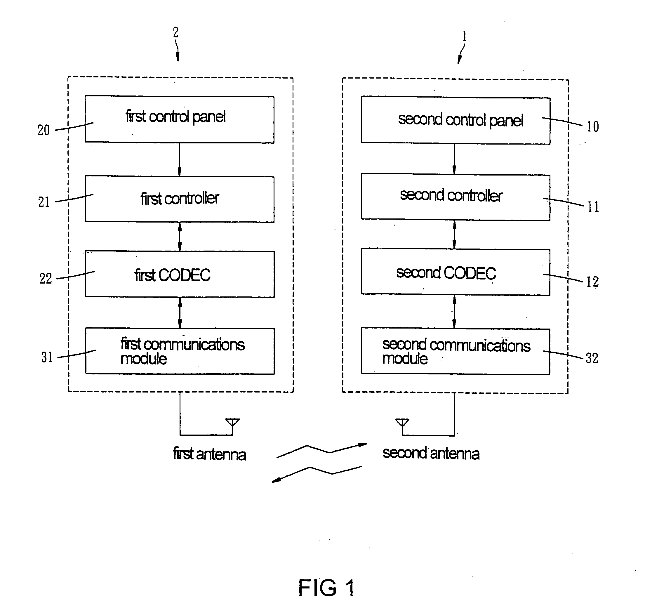
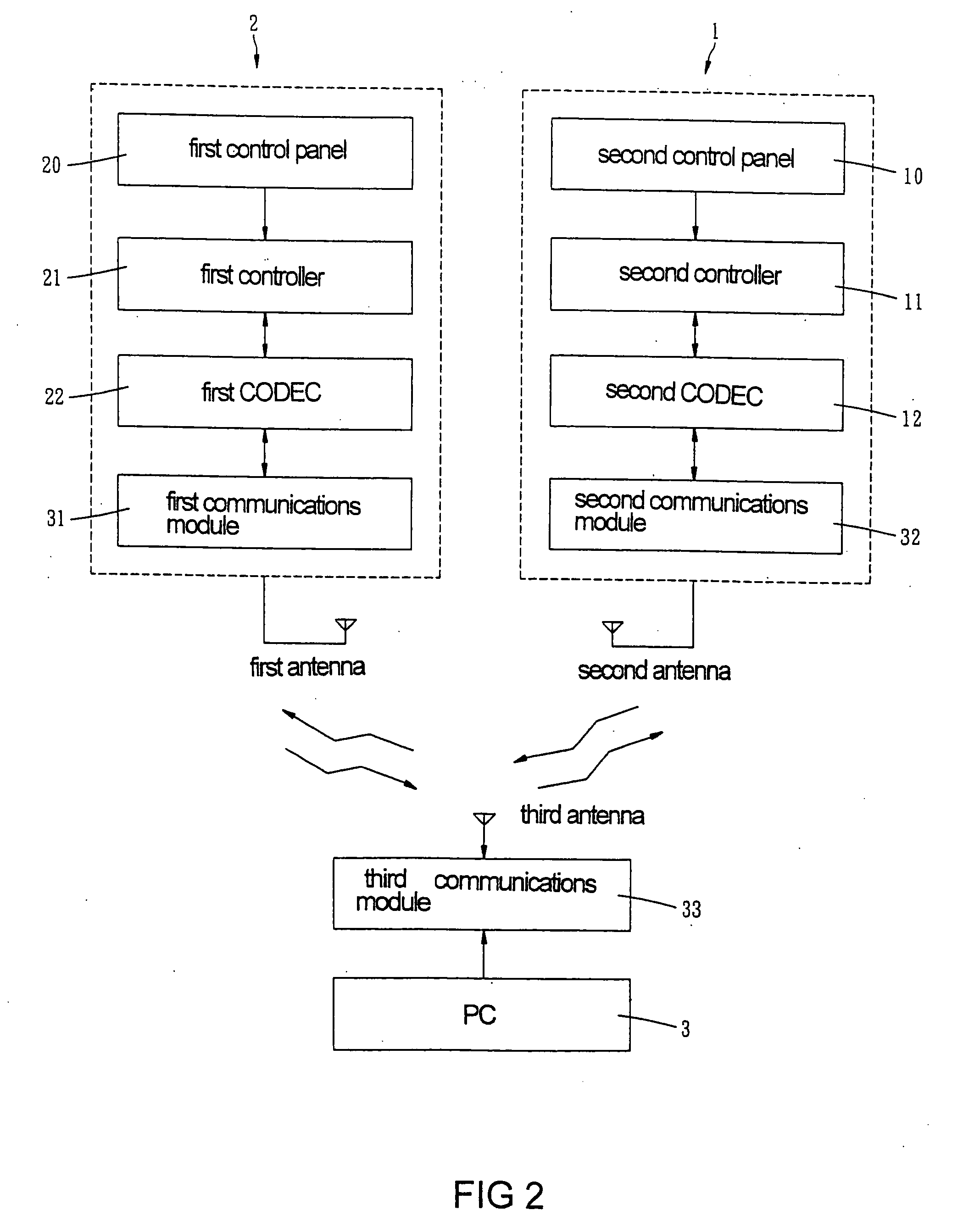
[0010]Referring to FIG. 1, a communications system in accordance with a first preferred embodiment of the invention is shown. The system comprises a wireless microphone 1 and a wireless transceiver 2. Note that the system can comprises a plurality of wireless microphones in other embodiments. Each component is discussed in detailed below.

[0011]The transceiver 2 comprises a first control panel 20, a first controller 21 on the first control panel 20 for setting a channel, transmission power, and a transmission range, a first codec 22 in the first control panel 20, a first communications module 31 in the first control panel 20, and a first antenna (not numbered) extending out of the housing of the transceiver 2.

[0012]Likewise, the microphone 1 comprises a second control panel 10, a second controller 11 on the second control panel 10 for setting a channel, transmission power, and a transmission range, a second codec 12 in the second control panel 10, a second communications module 32 in...


PUM


Abstract

In one embodiment a communications system includes at least one wireless microphone having a communications modules and a wireless transceiver also having a communications modules. In one operation the transceiver is adapted to send data to each microphone after setting a common operating frequency and ID. A PC having a wireless communications module is provided in another embodiment. The PC is adapted to activate the transceiver to send data to each microphone through its communications module. Each communications modules is complied with IEEE 802.15.4 standard.

Description

BACKGROUND OF THE INVENTION[0001]1. Field of Invention[0002]The invention relates to wireless communications system and more particularly to such a system comprising at least one wireless microphone, and a wireless transceiver which is adapted to send data to each microphone after setting a common operating frequency and ID.[0003]2. Description of Related Art[0004]Typically, electrical devices including microphones and stereos are connected to wall outlets in a room of a KTV center. One drawback is that wires may get tangled.[0005]Still typically, as an improvement of the above arrangement, the microphones are replaced with wireless ones. Also, one or more controllers are provided in which each controller is adapted to control two wireless microphones. Thus, for example, three controllers are required to control six wireless microphones. This inevitably will increase operating cost greatly. Thus, the need for improvement still exists.SUMMARY OF THE INVENTION[0006]It is therefore one...

Claims


Application Information

Patent Timeline
IPC IPC(8): H04B7/00H04M1/00
CPCH04R1/00H04W72/00H04W8/26
Inventor CHUNG, MING-CHENG
Owner JTS PROFESSIONAL
Why Eureka
Try Eureka