Control apparatus for hybrid vehicle power transmitting system

a technology of power transmission system and control apparatus, which is applied in the direction of electric propulsion mounting, vehicle sub-unit features, gearing, etc., can solve the problem of excessive rise of the operating speed of the vehicle drive electric motor, and achieve the effect of reducing or eliminating the risk of excessive rise of the operating speed of the electric motor

Inactive Publication Date: 2009-01-22
TOYOTA JIDOSHA KK
View PDF2 Cites 9 Cited by
  • Summary
  • Abstract
  • Description
  • Claims
  • Application Information

AI Technical Summary

Benefits of technology

[0007]The present invention was made in view of the background art described above. It is therefore an object of this invention to provide a control apparatus for a hybrid vehicle power transmitting system, which control apparatus is configured to reduce or eliminate a risk of an excessive rise of the operating speed of electric motors, etc. by suitably restricting the switching of the power transmitting path between the power transmitting state and the power cut-off state.

Problems solved by technology

Hence, the control apparatus disclosed in the publication is not configured to suitably control a switching portion of the power transmitting system provided to switch the power transmitting path between the power transmitting state and the power cut-off state, for reducing the risk of the excessive rise of the operating speed of the vehicle drive electric motor.

Method used


Image

  • Control apparatus for hybrid vehicle power transmitting system
  • Control apparatus for hybrid vehicle power transmitting system
  • Control apparatus for hybrid vehicle power transmitting system

Examples


first embodiment

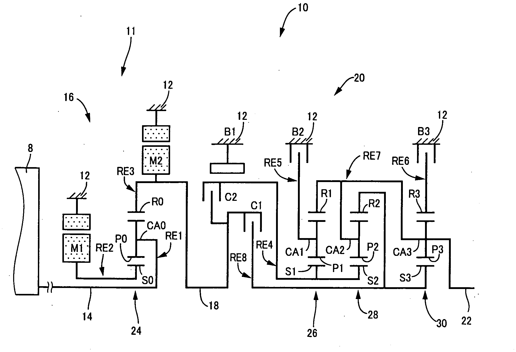
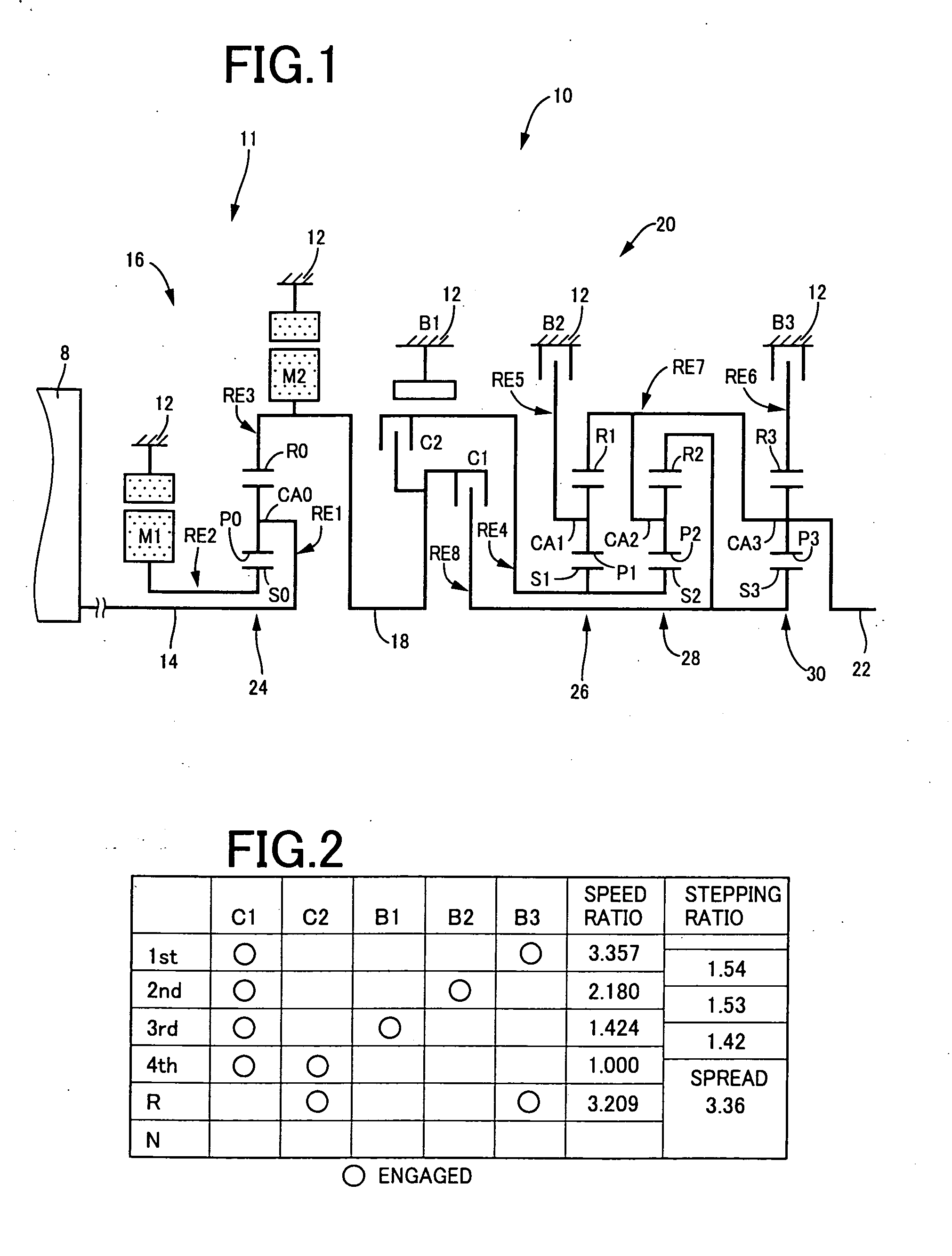
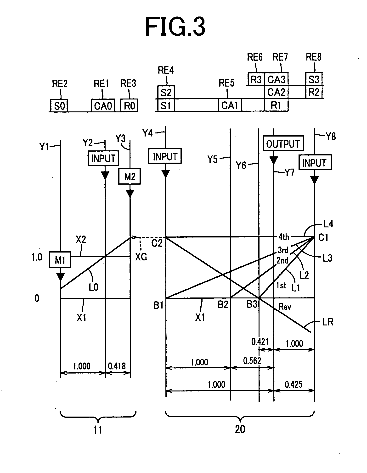
[0068]Referring first to the schematic view of FIG. 1, there is shown a transmission mechanism 10 constituting a part of a power transmitting system for a hybrid vehicle, which power transmitting system is controlled by a control apparatus constructed according to a first embodiment of this invention. As shown in FIG. 1, the transmission mechanism 10 includes: an input rotary member in the form of an input shaft 14; a continuously-variable transmission portion in the form of a differential portion 11 connected to the input shaft 14 either directly, or indirectly via a pulsation absorbing damper (vibration damping device) not shown; a power transmitting portion in the form of a hydraulic automatic transmission portion 20 disposed between the differential portion 11 and drive wheels 34 (shown in FIG. 7) of the hybrid vehicle, and connected in series via a power transmitting member 18 (power transmitting shaft) to the differential portion 11 and the drive wheels 34; and an output rotar...

second embodiment

[0141]When the shift lever 52 is operated by the vehicle operator from the forward-drive position D to the neutral position N during running of the vehicle, for example, the automatic transmission portion 20 is brought into the neutral state in which the power transmitting path between the second electric motor M2 and the drive wheels 34 is placed in the power cut-off state. In this power cut-off state, a load acting in a direction that reduces a rise of the rotating speed of the power transmitting member 18 which is the output shaft of the differential portion 11 is abruptly reduced, causing a rapid rise of the operating speed of the second electric motor M2 connected to the power transmitting member 18, which rapid rise adversely influences the durability of the second electric motor M2. In view of this drawback, an electronic control device 110 (shown in FIG. 4) according to the second embodiment of the present invention is configured to reduce or eliminate a risk of an excessive...

third embodiment

[0164]In the transmission mechanism 10, the second electric motor M2 is connected to one of two rotary members of the first clutch C1 (provided as a coupling element), so that the rotating speed of the rotary member of the first clutch C1 connected to the second electric motor M2, as well as the operating speed of the second electric motor M2, is rapidly raised when the power transmitting path through the automatic transmission portion 20 is brought into the power cut-off state as a result of the operation of the shift lever 52 from the drive position D, M to the neutral position. The rapid rise of the rotating speed of the rotary member of the first clutch C1 adversely influences the durability of the first clutch C1. In view of this drawback, an electronic control device 130 (shown in FIG. 4) according to the third embodiment of the present invention is configured to reduce or eliminate a risk of an excessive rise of the rotating speed of the above-indicated rotary member of the f...


PUM


Abstract

A control apparatus for a hybrid vehicle power transmitting system including a switching portion operable to switch a power transmitting path between a power transmitting state and a power cut-off state in response to an operation of a shift lever, the control apparatus including (a) an operating-state estimating portion configured to estimate an operating speed of an electric motor which constitutes a part of the power transmitting path or a rotating speed of a coupling element of the coupling portion, which speed is established after switching of the power transmitting path from one of the power transmitting and cut-off states to the other, and (b) a switching restricting portion configured to restrict a switching operation to switch the power transmitting path between the two states, when the estimated operating or rotating speed of the electric motor or coupling device is higher than a predetermined upper limit.

Description

CROSS REFERENCE TO RELATED APPLICATION[0001]The present application claims priority from Japanese Patent Application No. 2007-138355, which was filed on May 24, 2007, the disclosure of which is herein incorporated by reference in its entirety.BACKGROUND OF THE INVENTION[0002]1. Field of the Invention[0003]The present invention relates in general to a control apparatus for a hybrid vehicle power transmitting system, and more particularly to techniques for reducing a risk of an excessive rise of operating speeds of electric motors and a clutch provided in the power transmitting system.[0004]2. Discussion of Prior Art[0005]There is known a control apparatus for a power transmitting system of a hybrid vehicle provided with an engine, an electric generator and a vehicle drive electric motor, which control apparatus is arranged to reduce a torque of the engine for reducing a risk of an excessive rise of the operating speed of the vehicle drive electric motor, when the operating speed of t...

Claims


Application Information

Patent Timeline
Patent Type & Authority Applications(United States)
IPC IPC(8): F16H48/20B60K6/445B60K6/547B60L15/20B60L50/16B60W10/02B60W10/06B60W10/08B60W20/00
CPCB60K1/02Y10T477/26B60K6/445B60K6/547B60L2240/421B60L2240/441B60L2240/445B60L2240/485B60L2240/486B60W10/06B60W10/08B60W10/115B60W20/00B60W2510/0638B60W2510/0676B60W2510/068B60W2510/0685B60W2510/081B60W2510/1005B60W2510/107B60W2520/10B60W2520/105B60W2520/28B60W2530/10B60W2540/10B60W2540/12B60W2710/0605B60W2710/0616B60W2710/0666B60W2710/081F16H2037/0873Y02T10/6286Y02T10/642Y02T10/7258Y02T10/84Y02T10/6239Y10S903/946B60Y2400/435Y10T477/753B60K6/365Y02T10/62Y02T10/64Y02T10/72B60W20/10
Inventor IWASE, YUJIMATSUBARA, TOORUSHIBATA, HIROYUKITABATA, ATSUSHI
Owner TOYOTA JIDOSHA KK
Why Eureka
Try Eureka