Table engageable support for head cushion supporting anesthetized patient

a technology for anesthesia patients and support posts, which is applied in the direction of sofas, television systems, tables, etc., can solve the problems of eye damage threat, patient care challenges, and patients under general anesthesia are especially threatened, and achieve the effect of lateral shock dampening ability and easy adjustmen

Active Publication Date: 2009-01-29
MAZZEI WILLIAM J +2
View PDF3 Cites 32 Cited by
  • Summary
  • Abstract
  • Description
  • Claims
  • Application Information

AI Technical Summary

Benefits of technology

[0013]The pins projecting from the top surface provide a number of other functions that may be used singularly or in combination to provide the most utility from the device. First, the pins have a spiral slot about their exterior surface which form the pins into a spring-like structure with a leg engaging tip. This spring-like structure provides a means for vertical shock absorption to the head of the patient when weight from the head bears down on the cushion or on the cushion engaged with the casing. The spiraled pins engaging the cushion or casing also provide a lateral shock dampening ability in that if the head of the patient engaged in the cushion is moved sideways from body movement, the pins will tend to flex laterally allowing the casing and the cushion to move sideways substantially parallel to the top surface for a short distance. This sideways flexibility provides a second or lateral s...

Problems solved by technology

Surgeries upon patients in the prone position present a number of patient care challenges to the anesthesiologist and surgical staff.
Consequently, patients under general anesthesia are especially threatened by a number of factors, other than the surgery itself, which arise during such surgical procedures.
One hazard which requires constant vigilance by the surgical staff to protect against injury is the threat of eye damage.
Inadvertent pressure upon the ocular structures of a patient for just a matter of minutes can cause extreme damage or blindness to the eye.
As noted above, because the anesthetized patient is...

Method used


Image

  • Table engageable support for head cushion supporting anesthetized patient
  • Table engageable support for head cushion supporting anesthetized patient
  • Table engageable support for head cushion supporting anesthetized patient

Examples


Embodiment Construction

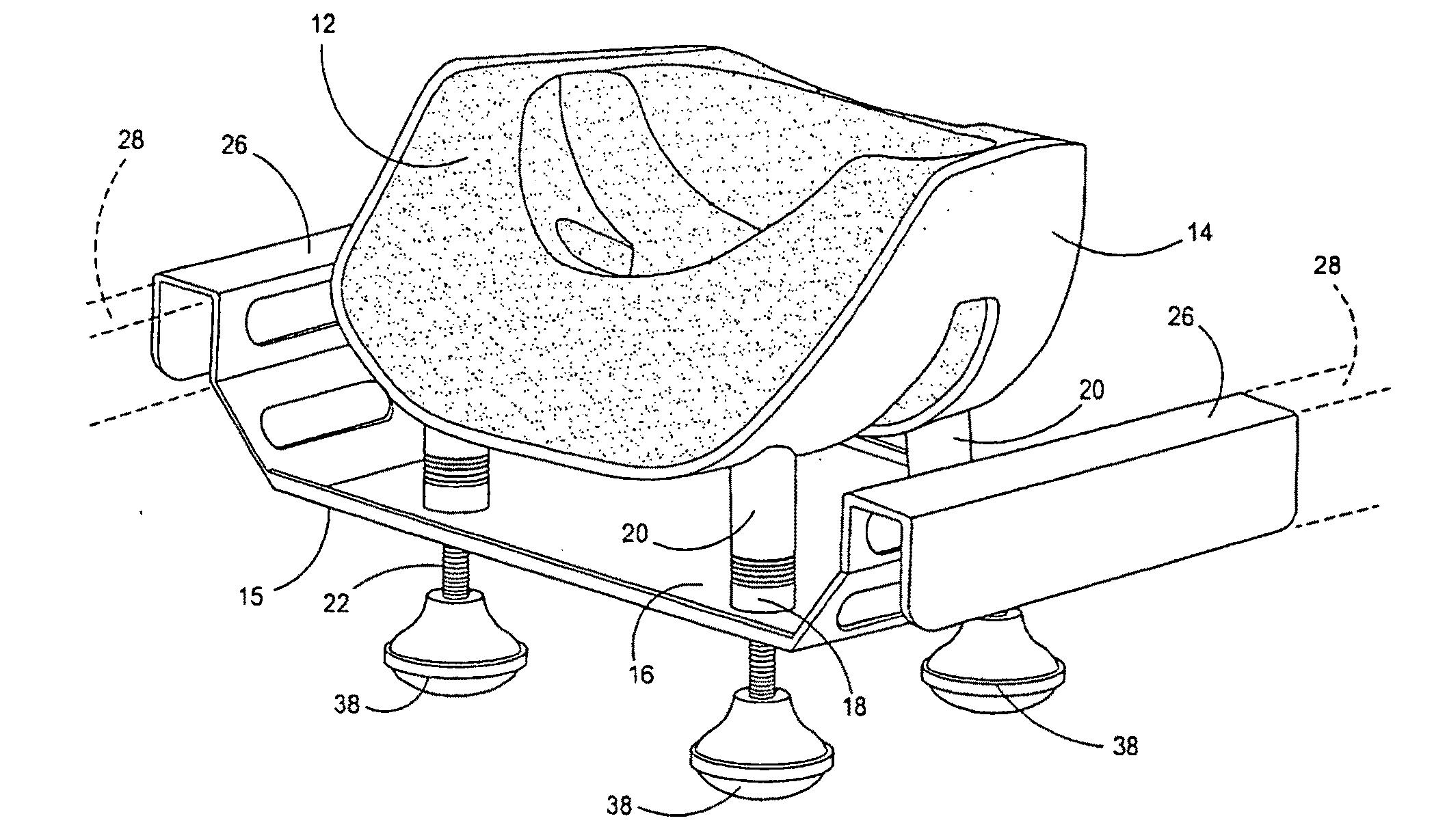
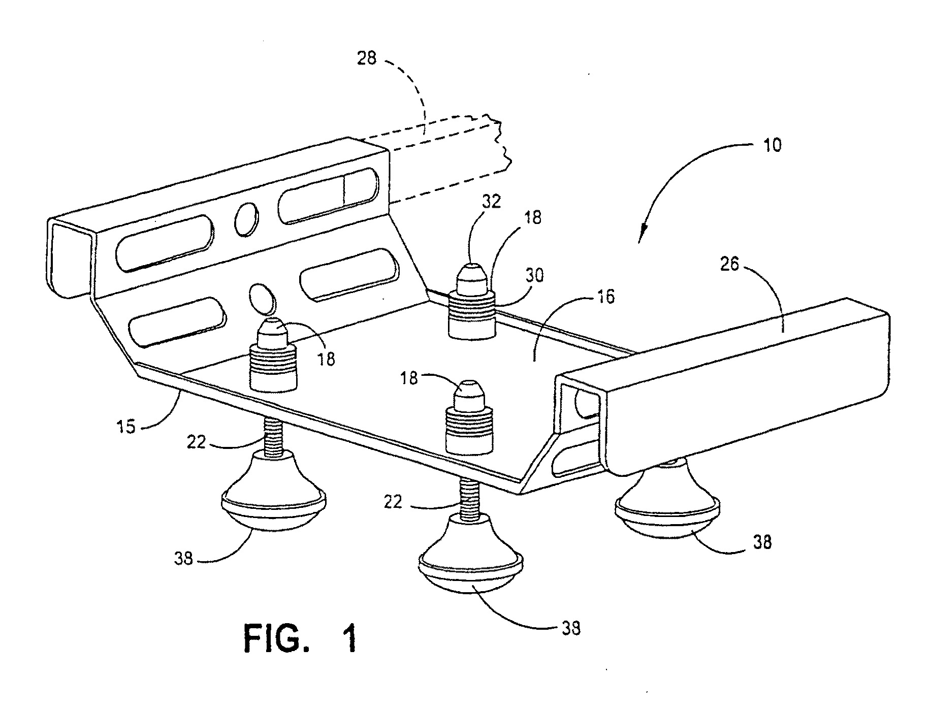
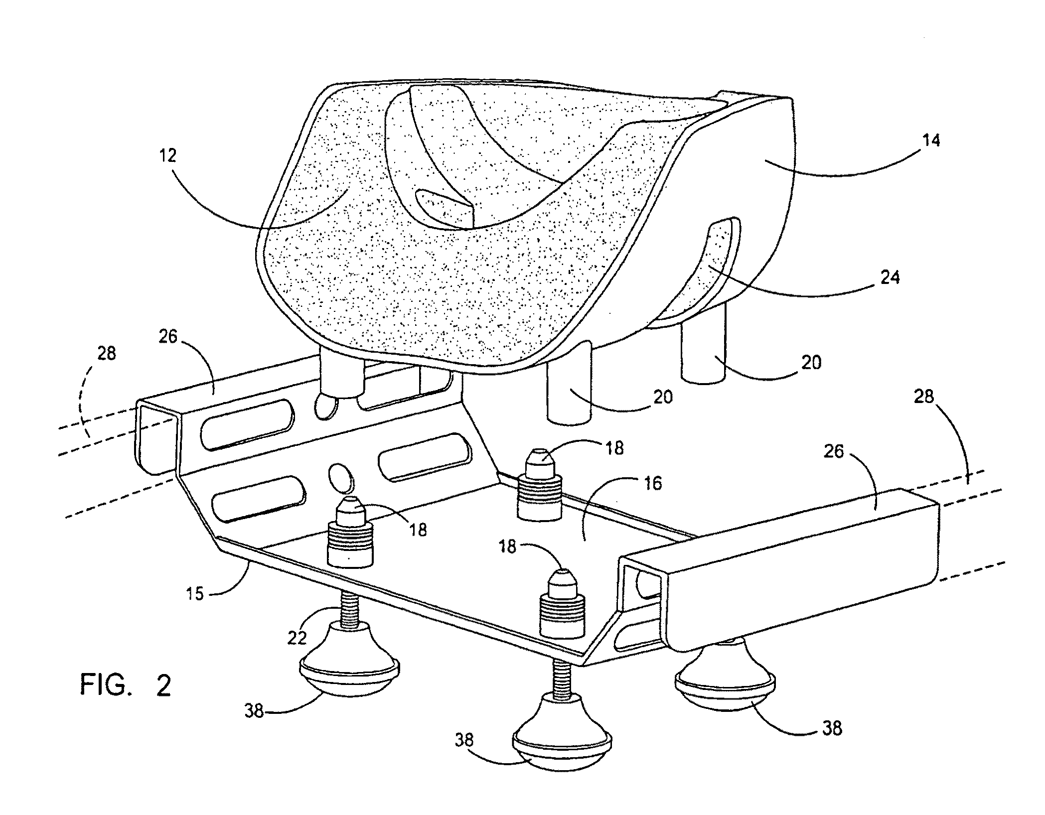
[0036]Referring now to the drawings, FIGS. 1-7 depict the various embodiments and engagements of the disclosed table engageable support device 10 for engagement with the head cushion 12 or cushion 12 engaged with a casing 14.

[0037]The device 10 herein disclosed is designed to cooperatively engage between the head supporting cushions 12, or the engaged cushion 12 and casing 14 and provide adjustable support to the head of a patient on an operating table. As shown in different embodiments in the figures, the device 10 has a tray 15 with a top surface 16 which is adapted to cooperatively engage with the cushion 12 by itself if the head support cushion 12 is used without a cooperatively engaged casing 14.

[0038]In a preferred mode of the device 10 the top surface 16 of the tray 15 has a plurality of projections extending therefrom in a spaced arrangement in the form of pins 18 adapted for engagement with detents or other engagement means in the exterior surface of a supported cushion 12 ...


PUM


Abstract

A support for the head of a patient lying in a generally prone position. The support features a tray adapted for support on an underlying operating table surface. A plurality of pins projecting from an engagement with the tray are positioned to engage and suspend either a cushion directly or a cushion engaged in a casing. The pins may be adjusted to raise or lower the engaged cushion or casing. A mirror is also provided to provide a reflective view a patient's eyes through slots in the cushion and casing engaged over a patient's face. A video camera may also concurrently be employed to capture electronic images of the patient's eyes and mouth through an aperture in the mirror.

Description

[0001]This application is a continuation in part of U.S. patent application Ser. No. 10 / 954,581 filed on Sep. 29, 2004 which claims priority from U.S. provisional application Ser. No. 60 / 507,624, filed Sep. 30, 2003, both of which are incorporated by reference herein in their entirety.BACKGROUND OF THE INVENTION[0002]1. Field of the Invention The present invention relates to a table engageable support for the head support or the cushion used for the head of an anesthetized patient. More particularly it relates to a tray which will either cooperatively mount upon struts projecting from the table used for supporting anesthetized patients, or engage the table by placing the tray portion upon the top of the operating table. The device has a top surface adapted to cooperatively engage with the pillow or pillow holder used to support the patient's head. It also can be configured with projections engaged with the side edges of the tray which then may engage with table struts commonly used ...

Claims


Application Information

Patent Timeline
IPC IPC(8): A47C20/02H04N7/18
CPCA61G2200/325A61G13/121
Inventor MAZZEI, WILLIAM J.JORDAN, GREGORY P.VU, AN B.
Owner MAZZEI WILLIAM J
Why Eureka
Try Eureka