Photographing apparatus, and control method and computer program product for controlling the same

Inactive Publication Date: 2009-01-29
FUJIFILM CORP
View PDF2 Cites 14 Cited by
  • Summary
  • Abstract
  • Description
  • Claims
  • Application Information

AI Technical Summary

Benefits of technology

[0010]The present invention has been developed in view of the circumstances described above, and it is an object of the present invention to enable a p

Problems solved by technology

If the camera shake correction system is driven at the time of light control exposure and then main photographing is performed, however, it is often the case that the camera shake correction system is not placed at the center

Method used


Image

  • Photographing apparatus, and control method and computer program product for controlling the same
  • Photographing apparatus, and control method and computer program product for controlling the same
  • Photographing apparatus, and control method and computer program product for controlling the same

Examples


first embodiment

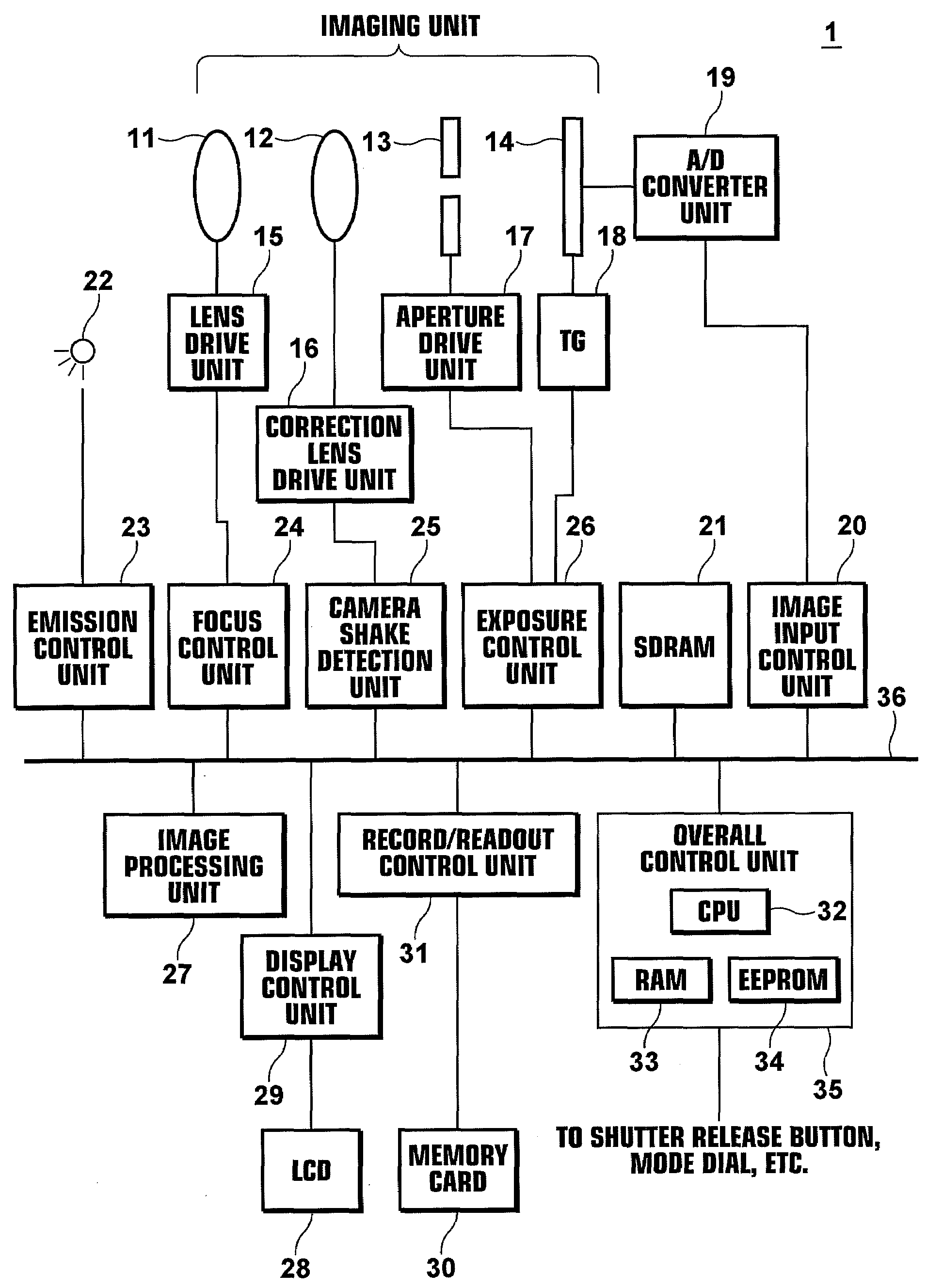
[0151]As described above, in the first embodiment, when performing light control exposure, the camera shake correction lens 12 is returned to the center of drive prior to the light control exposure period, and the camera shake correction lens 12 is returned to the center of drive after the light control exposure. This allows the camera shake correction lens 12 to be driven maximally in any direction within the drive range before light control exposure and before main photographing. Thus, camera shake correction may be performed efficiently at the time of light control exposure and main photographing.

[0152]Further, if the camera shake correction lens 12 is not placed at the center of drive when the release button 2 is fully depressed, the camera shake correction lens 12 is driven to the center of drive, so that the camera shake correction lens 12 may be driven always from the center of drive at the time of light control exposure.

[0153]In the first embodiment, it is desirable that the...

second embodiment

[0163]As described above, in the second embodiment, the drive range of the camera shake correction lens 12 is restricted during a period from the time when the first operational instruction is received to the time when the second operational instruction is received. This allows the camera shake correction lens 12 to be returned promptly when the second operational instruction is received, which results in efficient camera shake correction at the time of light control exposure and main photographing.

[0164]In the second embodiment, the drive range of the camera shake correction lens 12 is restricted during a period from the time when the first operational instruction is received to the time when the second operational instruction is received by limiting the drive range narrower than that during the light control exposure and main photographing. The drive range may be restricted by lessening the amount of camera shake correction, that is, by lessening the drive amount of the camera sha...

third embodiment

[0170]As described above, in the third embodiment, the camera shake correction lens 12 is driven to the center of drive during the emission period of red-eye reduction light. This allows the camera shake correction lens 12 to be returned to the center of drive without affecting light control exposure and main photographing through the use of a period that does not require camera shake correction.

[0171]In the third embodiment, the camera shake correction lens 12 is driven to the center of drive during the emission period of red-eye reduction light. But an arrangement may be adopted in which the camera shake correction lens 12 is returned to the center of drive during a period after the emission of red-eye reduction light to the time when light control exposure is performed.

[0172]Next, a fourth embodiment of the present invention will be described. The structure of a digital camera according to the fourth embodiment is identical to that of the digital camera 1 according to the first e...


PUM


Abstract

A photographing apparatus including: a photographing means that photographs a subject to obtain an image representing the subject by receiving an instruction to perform photographing; a camera shake correction means constructed to be driven in a direction different from the optical axis of the photographing means and corrects a camera shake induced blur of an image to be obtained by the photographing; and a correction system driving means that receives an instruction to perform main photographing and initiates driving of the camera shake correction means from a first predetermined position during a period from the time when the instruction to perform main photographing is given to the time when the subject is photographed, and drives the camera shake correction means to a second predetermined position during a period from the time when the driving is initiated to the time when the main photographing is performed.

Description

BACKGROUND OF THE INVENTION[0001]1. Field of the Invention[0002]The present invention relates to a photographing apparatus, such as a digital camera or the like, having a camera shake correction function and a control method of the apparatus. The invention also relates to a computer program product for causing a computer to perform the control method.[0003]2. Description of the Related Art[0004]Digital cameras having a camera shake correction function that prevents an image blur arising from a camera shake at the time of photographing are proposed. The camera shake correction function prevents a camera shake induced blur of an image to be obtained by photographing by detecting an amount of camera shake caused by hand movement using a camera shake sensor, such as an acceleration sensor or the like, and driving a camera shake correction lens constituting a taking lens or a camera shake correction system constituted by an image sensor, such as a CCD or the like, in the direction opposi...

Claims


Application Information

Patent Timeline
IPC IPC(8): G03B17/00H04N5/228
CPCG03B17/00H04N5/2328H04N5/23258H04N5/23248H04N23/68H04N23/685H04N23/6812
Inventor TAMURA, KAZUNORI
Owner FUJIFILM CORP
Why Eureka
Try Eureka