Wafer edge cleaning

a technology of cleaning edge and blade, applied in the direction of carpet cleaner, photosensitive materials, instruments, etc., can solve the problems of slurry particles still remaining, causing defects during subsequent processing, and slurry induced defects still occurring, etc., and achieving the effect of reducing the number of blades

Inactive Publication Date: 2009-02-05
APPLIED MATERIALS INC
View PDF17 Cites 5 Cited by
  • Summary
  • Abstract
  • Description
  • Claims
  • Application Information

AI Technical Summary

Problems solved by technology

Although these conventional cleaning devices remove a substantial portion of the slurry residue which adheres to wafer edges, slurry particles nonetheless may remain and produce defects during subsequent processing.
However, research shows that slurry induced defects still occur, and are caused by slurry residue remaining along the edges of the wafer despite cleaning with apparatuses such as that described above.
Specifically, subsequent processing has been found to redistribute slurry residue from the wafer edges to the front of the wafer, causing defects.
Although the edge-cleaning roller 21 addresses the need to clean slurry residue from wafer edges, it can be subject to quick wear, such wear typically being concentrated at locations where it contacts the wafer W.
Other rollers that may rotate in a common plane with a wafer W while contacting a portion of the wafer edge, but that perform additional or separate functions such as rotating the wafer W (e.g., drive rollers, such as the spinning mechanism 17a-c of FIG. 1) or guiding the rotating wafer W so as to limit or prevent tilting of the same (e.g., idling guide rollers (not separately shown)), are typically also subject to rapid wear where contact is made with the wafer W. The cost of maintaining proper operation of such parts and / or conducting frequent replacement of the same can mount quickly.

Method used


Image

  • Wafer edge cleaning
  • Wafer edge cleaning
  • Wafer edge cleaning

Examples


Embodiment Construction

Edge Cleaning Roller

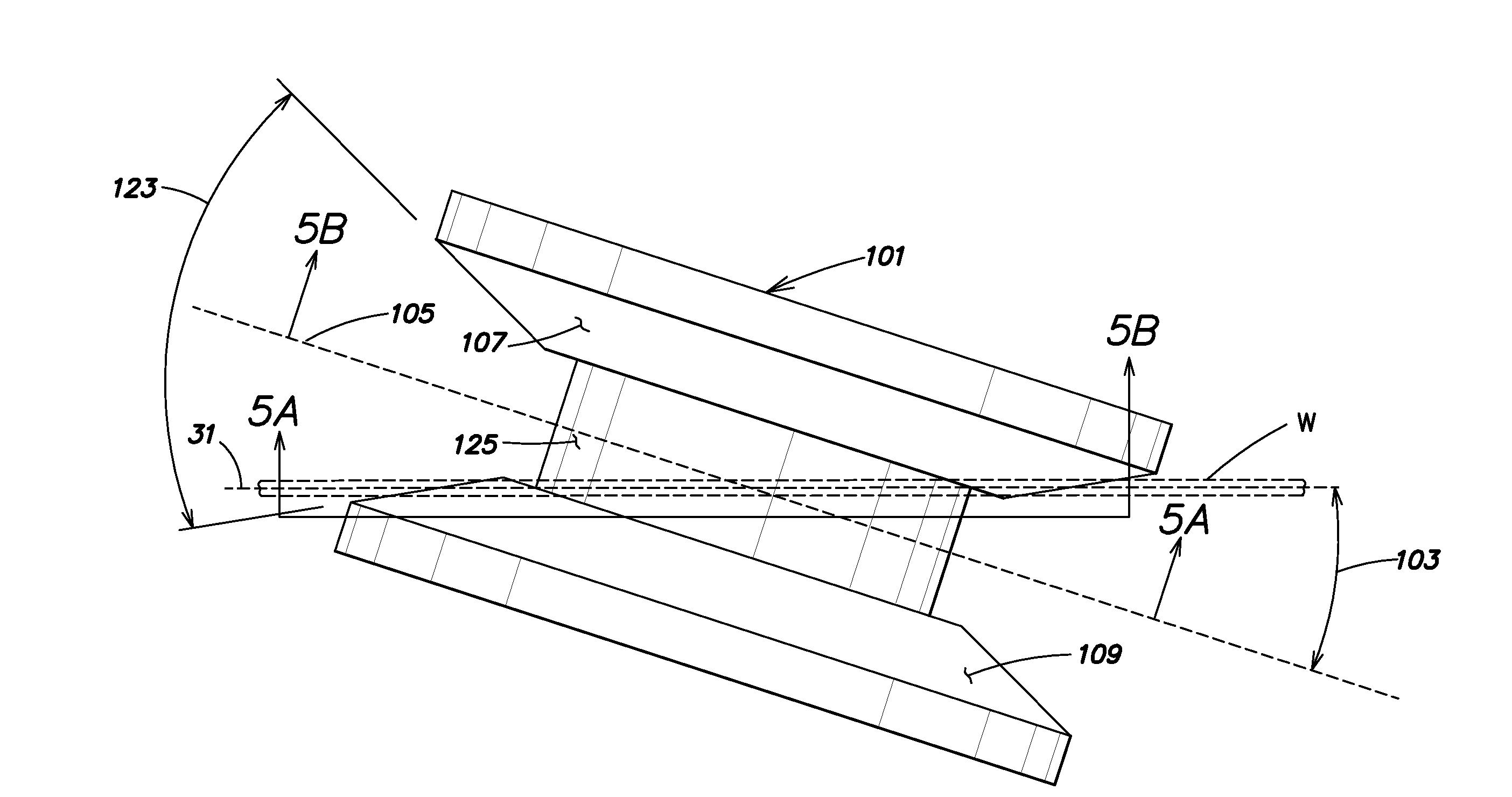
[0034]FIG. 4 is an side elevational view of an inventive edge-cleaning roller 101 in which the wafer W is shown in phantom across the edge-cleaning roller 101, the edge-cleaning roller 101 being adapted to contact edge surfaces (e.g., edge bevels as described above with reference to FIG. 3A) of the wafer W for cleaning. Where, as described above, the wafer W is supported and driven so as to rotate and remain within the nominal rotation plane 31 of the wafer W (rotation and support means for the same not being shown), the edge-cleaning roller 101 may be inventively oriented relative to the wafer W so as to form a first angle 103, the first angle 103 being that angle which is described between the nominal rotation plane 31 of the wafer W and a rotation plane 105 within which the edge-cleaning roller 101 is disposed and is adapted to rotate.

[0035]As shown in FIG. 4, the rotation plane 105 of the edge-cleaning roller 101 may be oriented relative to the nominal rotati...


PUM


Abstract

In a first aspect, an apparatus for cleaning a thin disk is provided. The apparatus includes a support roller for supporting a rotating wafer within a wafer cleaner. The support roller comprises a guide portion, for receiving an edge of a wafer, having an inclined surface comprising a low-friction material and adapted to allow the wafer edge to slide thereagainst; and an edge-trap portion for retaining the edge of the wafer and having a transverse surface comprising a high-friction material and adapted, when in communication with the edge of the wafer, to resist sliding thereagainst. Numerous other aspects are provided.

Description

[0001]This application is a division of, and claims priority to, U.S. Non-Provisional patent application Ser. No. 10 / 976,011, filed Oct. 28, 2004, and titled “WAFER EDGE CLEANING” (Attorney Docket No. 8186), which claims priority to U.S. Provisional Application Ser. No. 60 / 514,938, filed Oct. 28, 2003, and titled “WAFER EDGE CLEANING” (Attorney Docket No. 8186 / L). Both of these patent applications are hereby incorporated by reference herein in their entirety for all purposes.FIELD OF THE INVENTION[0002]The present invention relates generally to cleaning thin disks, such as semiconductor wafers, compact disks, glass substrates and the like. More particularly, the invention relates to scrubbing devices for simultaneously scrubbing the entire surface of a thin disk, including the edges thereof.BACKGROUND OF THE INVENTION[0003]To manufacture a thin disk such as a semiconductor wafer, an elongated billet of semiconductor material is cut into very thin slices or disks, about 2 mm in thick...

Claims


Application Information

Patent Timeline
Patent Type & Authority Applications(United States)
IPC IPC(8): B08B1/02B08B1/04B24B9/06H01L21/00
CPCB08B1/04H01L21/67046B24B9/065Y10S414/136
Inventor YUDOVSKY, JOSEPHCOULIN, ANNE-DOUCEVOLFOVSKI, LEON
Owner APPLIED MATERIALS INC
Why Eureka
Try Eureka