
Drinking cup cover

Inactive Publication Date: 2009-02-05
PRESIDENT PACKAGING INDAL CORP
View PDF4 Cites 5 Cited by
  • Summary
  • Abstract
  • Description
  • Claims
  • Application Information

AI Technical Summary

Benefits of technology

[0007]Therefore, the object of the present invention is to provide a drinking cup cover that can reduce user discomfort and avoid possible injury during beverage consumption.

Problems solved by technology

Because the tear line 123 was used to connect separably the tab part 121 to the periphery of the beverage hole 111, the periphery of the beverage hole 111 tends to be serrated when the tear line 123 is broken, thereby resulting in discomfort and possible injury when the user's lips come into contact with the periphery of the beverage hole 111 during beverage consumption.

Method used


Image

  • Drinking cup cover
  • Drinking cup cover
  • Drinking cup cover

Examples


Embodiment Construction

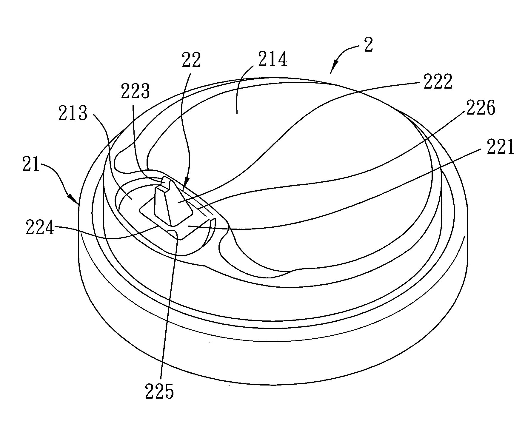
[0016]As illustrated in FIGS. 4 to 6, the preferred embodiment of a drinking cup cover 2 according to the present invention includes a cover body 21 and a closure member 22.

[0017]The cover body 21 has a cover wall 214 with a top surface 215, a bottom surface 216, and a peripheral portion 217. A beverage hole 212 is formed through the top and bottom surfaces 215, 216 of the cover wall 214 adjacent to the peripheral portion 217. The cover wall 214 further has a hole-defining periphery 211 that defines the beverage hole 212. In this embodiment, the cover wall 214 further has a recessed portion 213 adjacent to the peripheral portion 217 and indented from the top surface 215 of the cover wall 214. The beverage hole 212 is located in the recessed portion 213.

[0018]The closure member 22 has a tab part 221, a depressible part 222, and an engaging part 223. The tab part 221 is connected to the hole-defining periphery 211 such that the closure member 22 is movable relative to the cover body 2...


PUM


Abstract

A drinking cup cover includes a cover body and a closure member. The cover body has a cover wall with top and bottom surfaces, a peripheral portion, and a beverage hole formed through the top and bottom surfaces of the cover wall adjacent to the peripheral portion. The cover wall further has a hole-defining periphery that defines the beverage hole. The closure member includes a tab part, a depressible part, and an engaging part. The tab part is connected to the hole-defining periphery such that the closure member is movable relative to the cover body between a sipping position and a non-sipping position. The depressible part protrudes upwardly from the tab part and is operable to move the tab part downwardly from the non-sipping position to the sipping position. The engaging part is formed on one end of the depressible part opposite to tab part to engage the hole-defining periphery.

Description

BACKGROUND OF THE INVENTION[0001]1. Field of the Invention[0002]The invention relates to a drinking cup cover, more particularly to a drinking cup cover that permits sipping of a beverage therethrough.[0003]2. Description of the Related Art[0004]As illustrated in FIGS. 1 and 2, a conventional drinking cup cover 1 includes a cover body 11 and a closure member 12. The cover body 11 has a beverage hole 111 to permit sipping of a beverage, and a recess 112 proximate to the beverage hole 111. The closure member 12 is disposed at the beverage hole 111, and has a tab part 121 and a depressible part 122. The tab part 121 is connected to a periphery of the beverage hole 111 such that the closure member 12 is movable relative to the cover body 11 between a sipping position (see FIG. 2), where the tab part 121 uncovers the beverage hole 111, and a non-sipping position (see FIG. 1), where the tab part 121 spans the beverage hole 111. The depressible part 122 protrudes upwardly from the tab part...

Claims


Application Information

Patent Timeline
IPC IPC(8): A47G19/22
CPCB65D43/0212B65D47/0847B65D2251/1008B65D2543/00351B65D2543/00046B65D2543/00092B65D2543/00296B65D2251/1066
Inventor LEE, STEVENTU, CHENG-TI
Owner PRESIDENT PACKAGING INDAL CORP
Features
  • Generate Ideas
  • Intellectual Property
  • Life Sciences
  • Materials
  • Tech Scout
  • Unparalleled Data Quality
  • Higher Quality Content
  • 60% Fewer Hallucinations
Learn More