Handheld electronic apparatus and touch panel thereof

a technology of electronic equipment and touch panel, which is applied in the field of electronic equipment, can solve the problems of unfavorable user operation, non-user-friendly operation, and uncomfortable operation feeling, and achieve the effect of improving operation feeling

Inactive Publication Date: 2009-02-05
HTC CORP
View PDF3 Cites 22 Cited by
  • Summary
  • Abstract
  • Description
  • Claims
  • Application Information

AI Technical Summary

Benefits of technology

[0007]The present invention provides a handheld electronic apparatus and the touch panel thereof. The front cover and the touch panel of the handheld electronic apparatus are assembled, so that the front cover will not stick out from the touch panel. Accordingly, the problem of the difficult operation of the touch panel border can be resolved, thereby providing the user a better operation feeling.

Problems solved by technology

As wireless network technology progresses, traditional cellular phones using keys for input no longer meet the demand of users.
The border of the touch panel body 111 (i.e., the area of the touch panel body 111 connected to the front cover 12) is not easily accessed, causing non-user-friendly operation and uncomfortable operation feeling, and the border tends to become dirty because it is not easily cleaned.

Method used


Image

  • Handheld electronic apparatus and touch panel thereof
  • Handheld electronic apparatus and touch panel thereof
  • Handheld electronic apparatus and touch panel thereof

Examples


first embodiment

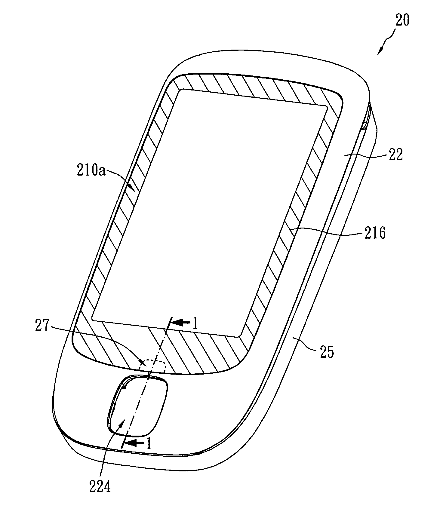
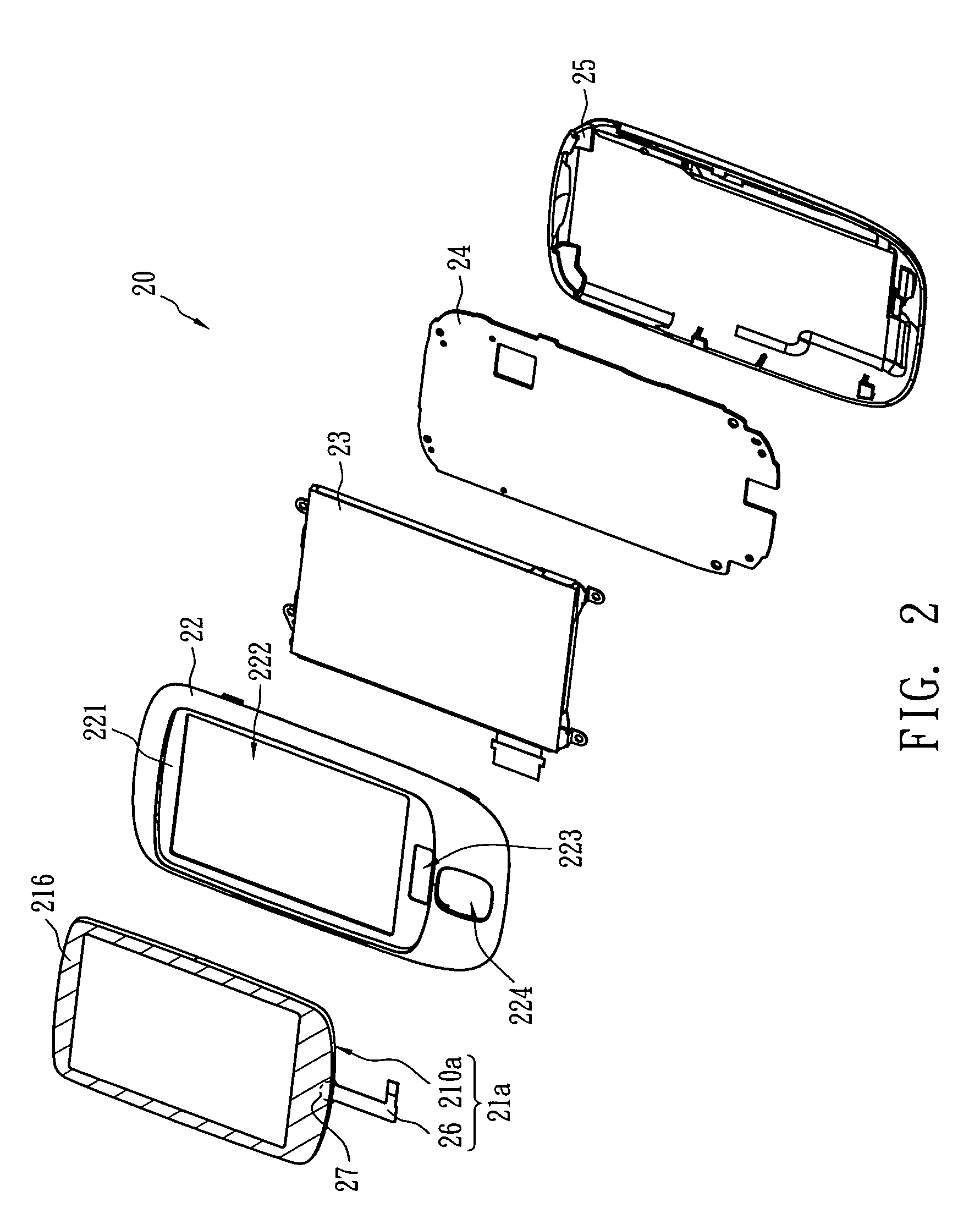
[0020]FIG. 5 illustrates a cross-sectional view of a touch panel in accordance with the present invention, which is a resistive touch panel of a film / glass type. The touch panel 21a is a multi-layer structure, and comprises a touch panel body 210a and a flexible printed circuit 26. The flexible printed circuit 26 is connected to the touch panel body 210a. The touch panel body 210a comprises a first substrate 211, a first transparent conductive layer 212, a plurality of spacers 213, an insulation layer 216, a second transparent conductive layer 214 and a second substrate 215. The first substrate 211 is placed on the support portion 221 and covers the first opening 222, and the first substrate 211 has a notch 27. The first transparent conductive layer 212 is placed on the first substrate 211. The second transparent conductive layer 214 is placed above the first transparent conductive layer 212, and is separated from the first transparent conductive layer 212 by the insulation layer 21...

second embodiment

[0024]FIG. 6 is a cross-sectional view of the touch panel in accordance with the present invention, which is of the so-called film / film / glass type. The touch panel 21b comprises a touch panel body 210b and a flexible printed circuit 26. The flexible printed circuit 26 is connected to the touch panel body 210b. The touch panel body 210b comprises a first substrate 211, a glue layer 217, a third substrate 218, a first transparent conductive layer 212, an insulation layer 216, multiple spacers 213, a second transparent conductive layer 214 and a second substrate 215. In comparison with the embodiment shown in FIG. 5, the third substrate 218 is further formed between the first substrate 211 and the first transparent conductive layer 212, and the third substrate 218 is glued to the first substrate 211 by the glue layer 217.

[0025]More particularly, the bi-layer structure of the first transparent conductive layer 212 and the third substrate 218 is similar to the bi-layer structure of the s...


PUM


Abstract

A handheld electronic apparatus comprises a touch panel, a front cover and a display panel. The front cover has a support portion with a first opening. The touch panel is placed on the support portion and covers the first opening. The touch panel comprises a touch panel body and a flexible printed circuit (FPC). The touch panel body has a first substrate having a notch configured to accommodate one end of the flexible printed circuit connected to the touch panel body. When the touch panel is assembled with the front cover, the flexible printed circuit will not be too-sharply bent due to the notch design.

Description

BACKGROUND OF THE INVENTION[0001](A) Field of the Invention[0002]The present invention is related to an electronic apparatus, and more specifically, to a handheld electronic apparatus and the touch panel thereof.[0003](B) Description of Related Art[0004]A traditional Personal Digital Assistant (PDA) usually uses a touch panel as an input interface. As wireless network technology progresses, traditional cellular phones using keys for input no longer meet the demand of users. Therefore, an advanced cellular phone with a touch panel as the interface was introduced recently, and provided a brand new communication feeling.[0005]FIG. 1 illustrates a cross-sectional view of a cellular phone with a traditional touch panel. Referring to FIG. 1, a cellular phone with touch panel 10 comprises a touch panel 11, a front cover 12, a display panel 16 and a rear cover 18. The front cover 12 and the rear cover 18 are assembled to each other, and the touch panel 11 and the display panel 16 are dispos...

Claims


Application Information

Patent Timeline
Patent Type & Authority Applications(United States)
IPC IPC(8): G06F3/045H05K5/02
CPCG06F1/1626G06F1/1643H04M1/23H04M1/0266G06F1/1656
Inventor SHIH, CHIN CHUNGLU, HSUEH LIN
Owner HTC CORP
Why Eureka
Try Eureka