
Method and apparatus for graphically defining surface normal maps

surface normalization technology, applied in the field of computer generated animation, can solve the problems of curved surfaces not being perfectly smooth or uniform, the edge and interior lines are generally not perfectly straight or uniform in width, and it is difficult to tell from a surface normal map what the ultimate effect of a given perturbation is

Inactive Publication Date: 2009-02-05
DISNEY ENTERPRISES INC
View PDF13 Cites 9 Cited by
  • Summary
  • Abstract
  • Description
  • Claims
  • Application Information

AI Technical Summary

Benefits of technology

[0010]Accordingly some embodiments of the present invention provide visualization tools that facilitate a user's understanding of surface normal maps and the effect of making a change to a surface normal map. An intuitive visual interface allows a user (e.g., an art director, although a user could be anyone participating in the definition of an object to appear in a computer-generated image) to readily achieve a desired painterly style.

Problems solved by technology

For instance, edge and interior lines are generally not perfectly straight or uniform in width, curved surfaces do not look perfectly smooth or uniform, and so on.
In computer generated images, such non-uniformities can be recreated by perturbing surface normal maps, but it is difficult to tell from a surface normal map what the ultimate effect of a given perturbation will be.

Method used


Image

  • Method and apparatus for graphically defining surface normal maps
  • Method and apparatus for graphically defining surface normal maps
  • Method and apparatus for graphically defining surface normal maps

Examples


Embodiment Construction

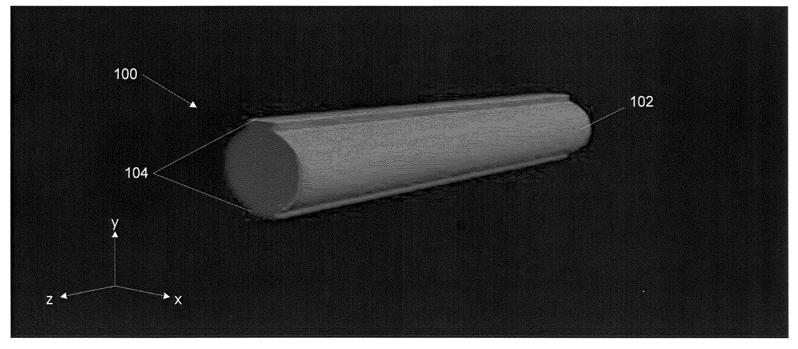
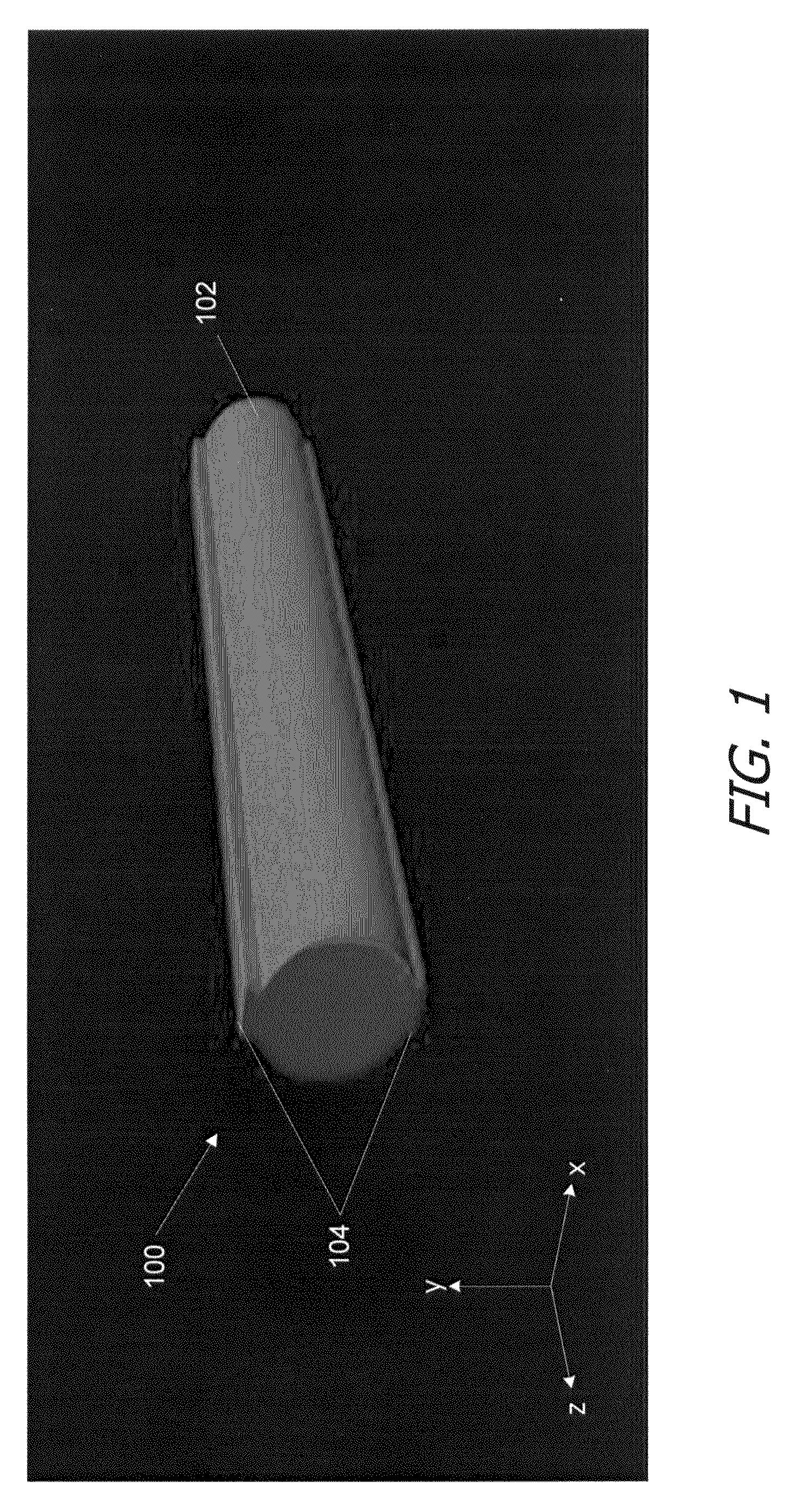
[0017]FIG. 1 illustrates a reference object 100, a cylinder 102 with flanges 104, for which surface normals are represented using a color map according to an embodiment of the present invention. In this embodiment, reference object 100 is defined in an (x, y, z) coordinate space (e.g., object space) with the axis of cylinder 102 aligned with the z axis and the y axis oriented vertically.

[0018]To aid in visualizing the surface normals, the x component of the surface normal at each point is mapped to a red color component (with higher red values reflecting larger x components), the y component to a green color component, and the z component to a blue color component. This mapping can be performed, e.g., in a paint program that allows a user (e.g., an art director) to define surface features of an object during modeling. Paint programs are known in the art. Such programs allow the user to view an image of an object, where the image is generated from the object model. A graphical user i...


PUM


Abstract

A surface normal map of an object can be interactively modified to create brushstroke-like textures. In one embodiment, surface normal components along the x, y, and z axes (in object coordinate space) are mapped onto red, green, and blue color components. The object's surface is displayed in an editing interface (e.g., a painting program) with colors indicating the surface normals. The user can then modify the surface normals to achieve a desired look for the object. The modified surface normals are stored with the object-model data and are used in rendering the object, helping to create a painted appearance.

Description

CROSS-REFERENCES TO RELATED APPLICATIONS[0001]This application claims the benefit of U.S. Provisional Application No. 60 / 953,665, filed Aug. 2, 2007, entitled “Method and Apparatus for Graphically Defining Surface Normal Maps,” which disclosure is incorporated herein by reference for all purposes.BACKGROUND OF THE INVENTION[0002]The present invention relates in general to computer-generated animation and in particular to graphically defining surface normal maps.[0003]Three-dimensional (3-D) animation generally begins with a geometric model of the objects that will appear in the animated scene. Each object is modeled, e.g., as a mesh of polygons in 3-D space, and various attributes of the object's surface are associated with points in the mesh, such as the vertices of the polygons. For example, attributes associated with a point often include a color, a surface normal, a transparency parameter, reflectivity parameters, and one or more sets of texture coordinates, allowing one or more...

Claims


Application Information

Patent Timeline
Patent Type & Authority Applications(United States)
IPC IPC(8): G09G5/00
CPCG06T15/04
Inventor MURRAH, JOHN T.LUSINSKY, DONALD ADOLPHDRISKILL, HENRY ALLENJENKINS, SEAN D.ECKART, COLINKINNEY, ANDREW
Owner DISNEY ENTERPRISES INC
Learn More