Illumination device

a technology of illumination device and led light, which is applied in the direction of waveguides, instruments, printing, etc., can solve the problems of reducing the ability of low power leds to properly illuminate objects, coupling, etc., and achieves the effects of high coupling efficiency, high light output, and simplified mechanical design and size of illumination devi

Inactive Publication Date: 2009-02-05
OPTIM
View PDF50 Cites 35 Cited by
  • Summary
  • Abstract
  • Description
  • Claims
  • Application Information

AI Technical Summary

Benefits of technology

[0005]In one aspect, the invention relates to an illumination device, such as, for example, an endoscope, a lamp, or a head light. The illumination device includes a light source including a substantially planar light-emitting surface and an optical rod or optical taper disposed proximate to the substantially planar light-emitting surface. By arranging the optical rod or optical taper in a proximate relationship to the substantially planar light-emitting surface, the two elements are coupled in a manner which allows a large amount of the light emitted by the light source to be transmitted directly into the optical rod or optical taper. As a result, a greater amount of light from the light source can be transmitted through the illumination device and onto an object for illumination. Embodiments of the present invention do not include auxiliary optics, such as lenses or mirrors, disposed between the light source and the optical rod or optical taper, but instead rely on the close placement (e.g., direct contact or close proximity) of the optical rod or taper to the planar light-emitting region of the light source. The lack of auxiliary optics between the light source and the optical rod or optical taper simplifies the mechanical design and space requirements for the illumination device. As a result, illumination devices in accordance with the presence invention, can be small and compact while providing the desired illumination strength.
[0010]Any of the above implementations can realize one or more of the following advantages. The illumination devices and methods described above are efficient at transmitting light from the light source into the optical rod or optical taper. As a result, objects can be illuminated with a proper amount of light (e.g., object is visible under endoscopic examination, object under a lamp is sufficiently lighted for viewing purposes). Another advantage realized in the above embodiments is that the optical rod or optical taper can be coupled to the light source without the use of additional optical components or auxiliary optics, such as, for example, mirrors, lenses, reflectors. As a result, a large amount of the light emitted by the light source can be coupled directly into the optical rod or optical taper, thereby allowing a greater amount of light from the light source to be transmitted to the objects under investigation. The lack of auxiliary optics between the light source and the optical rod or taper also simplifies the mechanical design and size of the illumination device. In addition, the high light output and high coupling efficiency of the light emitted by the light source into the optical rod or optical taper increases battery lifetime and thus permits the use of smaller capacity, and smaller volume batteries to power the illumination device.

Problems solved by technology

However, challenges remain with respect to coupling LEDs to optical transmission media, such as, for example, optical rods and optical tapers.
Generally, multiple LEDs are necessary because the light output from a single, low power LED is typically too weak to properly illuminate an object.
In addition, the arrangement of the multiple LEDs to the optical transmission media used in these prior attempts has resulted in unacceptable light loss, thereby further decreasing the low power LED's ability to properly illuminate an object.

Method used


Image

  • Illumination device
  • Illumination device
  • Illumination device

Examples


Embodiment Construction

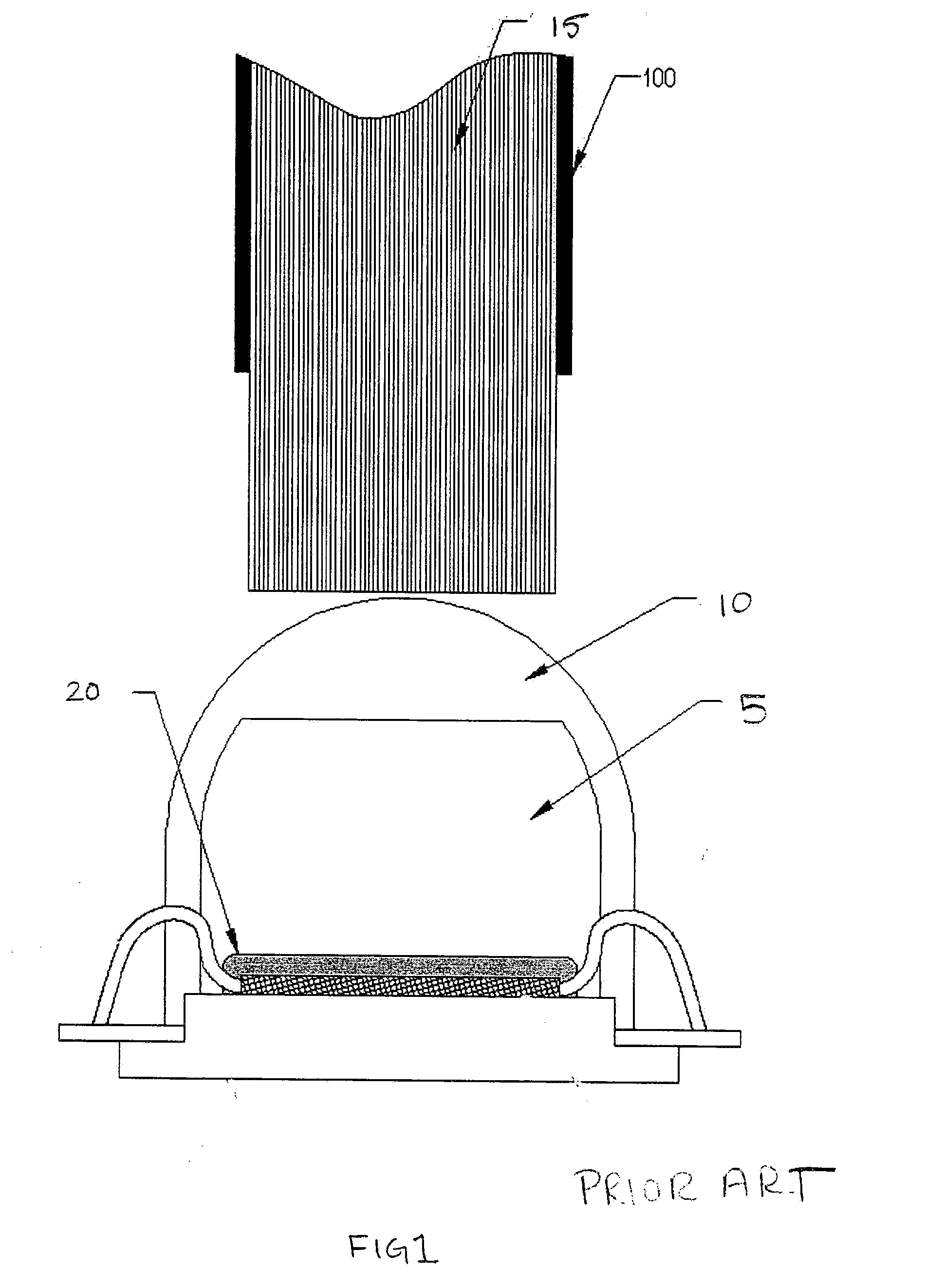
[0020]Prior art illumination devices, such as, for example, the illumination device shown in FIG. 1, include a light source 5 having a dome-shaped lens 10 optically coupled to transmission media 15. With this coupling arrangement, light is ineffectively transmitted to the transmission media 15 because the light emitting portion 20 of the light source 5 is not sufficiently close to the transmission media 15 (i.e., due to the curvature of the dome lens 10, the light emitting portion 20 is spaced at an unacceptable distance away from the transmission media). In addition, the dome shape lens 10 provides a convex light-emitting surface. As a result, a portion of the light passing through an interface between the light source 5 and the transmission media 15 is lost, thereby decreasing the light strength and efficiency of conventional illumination devices.

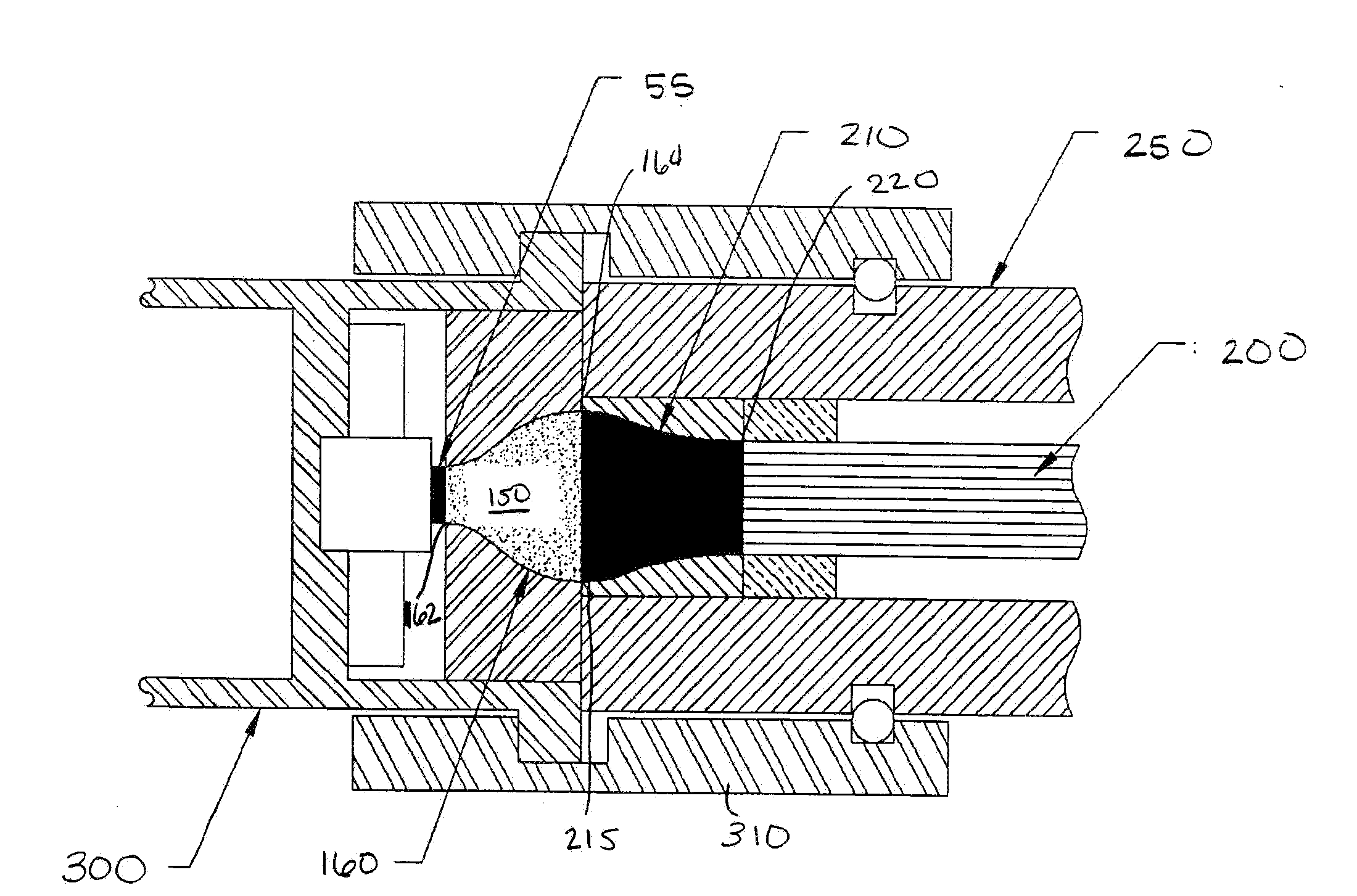
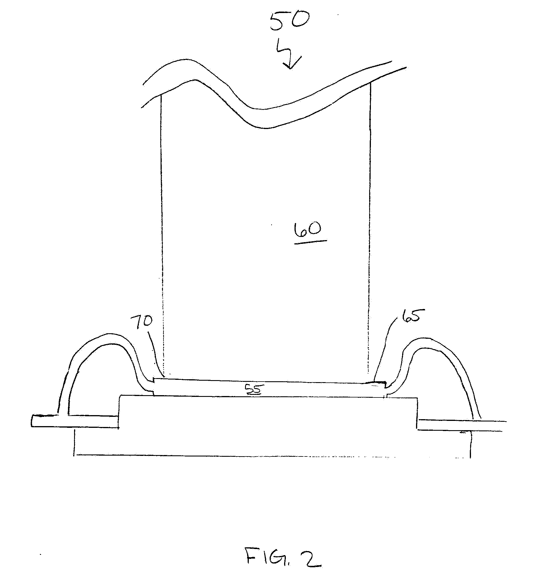
[0021]Illumination devices of the present invention include a substantially planar light-emitting surface which is proximate to either a...


PUM


Abstract

Illumination devices include a light source including a substantially planar light-emitting surface and an optical rod or optical taper disposed proximate to the substantially planar light-emitting surface to optically couple the optical rod and the substantially planar light-emitting surface.

Description

RELATED APPLICATIONS[0001]This application is a continuation application of U.S. patent application Ser. No. 11 / 323,481 filed on Dec. 30, 2005. U.S. patent application Ser. No. 11 / 323,481 is a continuation-in-part of U.S. patent application Ser. No. 10 / 810,504 filed on Mar. 26, 2004, which claims the benefit of U.S. Provisional Application No. 60 / 457,672, filed on Mar. 26, 2003. The entire disclosure of each of the above-referenced applications is incorporated herein by reference.FIELD OF THE INVENTION[0002]This invention relates to an illumination device including a substantially planar light-emitting surface coupled to an optical rod or optical taper.BACKGROUND OF THE INVENTION[0003]Advances in light source technology, such as, for example, light-emitting diode (LED) technology, have led to very bright and reliable solid state lamps. However, challenges remain with respect to coupling LEDs to optical transmission media, such as, for example, optical rods and optical tapers. While ...

Claims


Application Information

Patent Timeline
Patent Type & Authority Applications(United States)
IPC IPC(8): F21V5/00F21V8/00
CPCA61B1/07G02B6/0006G02B6/04G02B6/4206G02B6/421F21K9/52A61B1/0684G02B19/0028G02B19/0061Y10S385/901G02B6/4298F21K9/61
Inventor KRUPA, ROBERT J.ROOT, THOMAS V.
Owner OPTIM
Why Eureka
Try Eureka