Wheel chock With Restraint

a technology of restraint and wheel, which is applied in the direction of braking system, transportation and packaging, transportation items, etc., can solve the problem of not preventing upward movement of the vehicl

Active Publication Date: 2009-02-05
MIDWEST PRECISION PRODS
View PDF7 Cites 43 Cited by
  • Summary
  • Abstract
  • Description
  • Claims
  • Application Information

AI Technical Summary

Problems solved by technology

The system resists fore-and-aft vehicle movement with angled ramps, and also resists lateral vehicle movement, but does not prevent upward movement of the vehicle.
Thus,

Method used


Image

  • Wheel chock With Restraint
  • Wheel chock With Restraint
  • Wheel chock With Restraint

Examples


Embodiment Construction

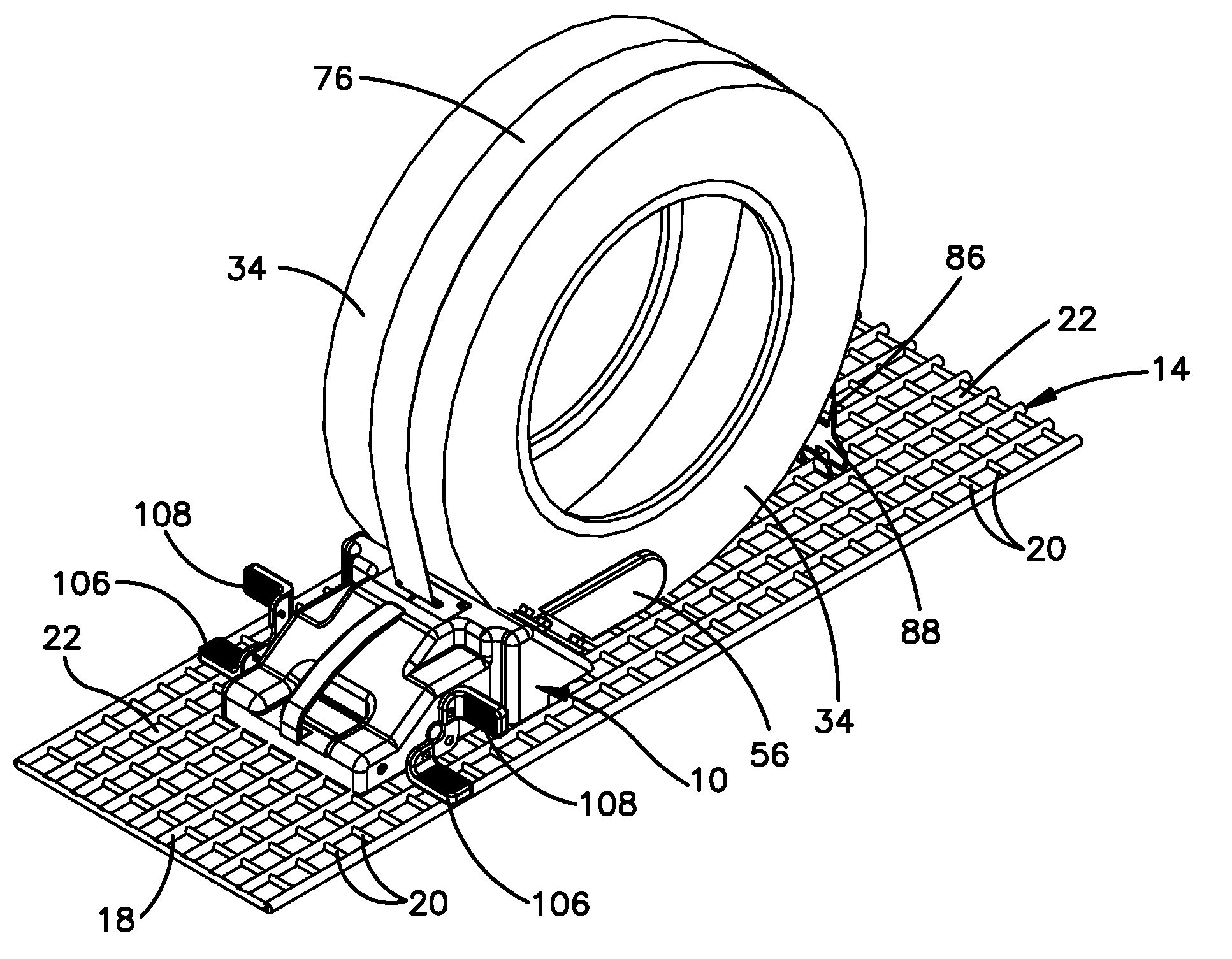
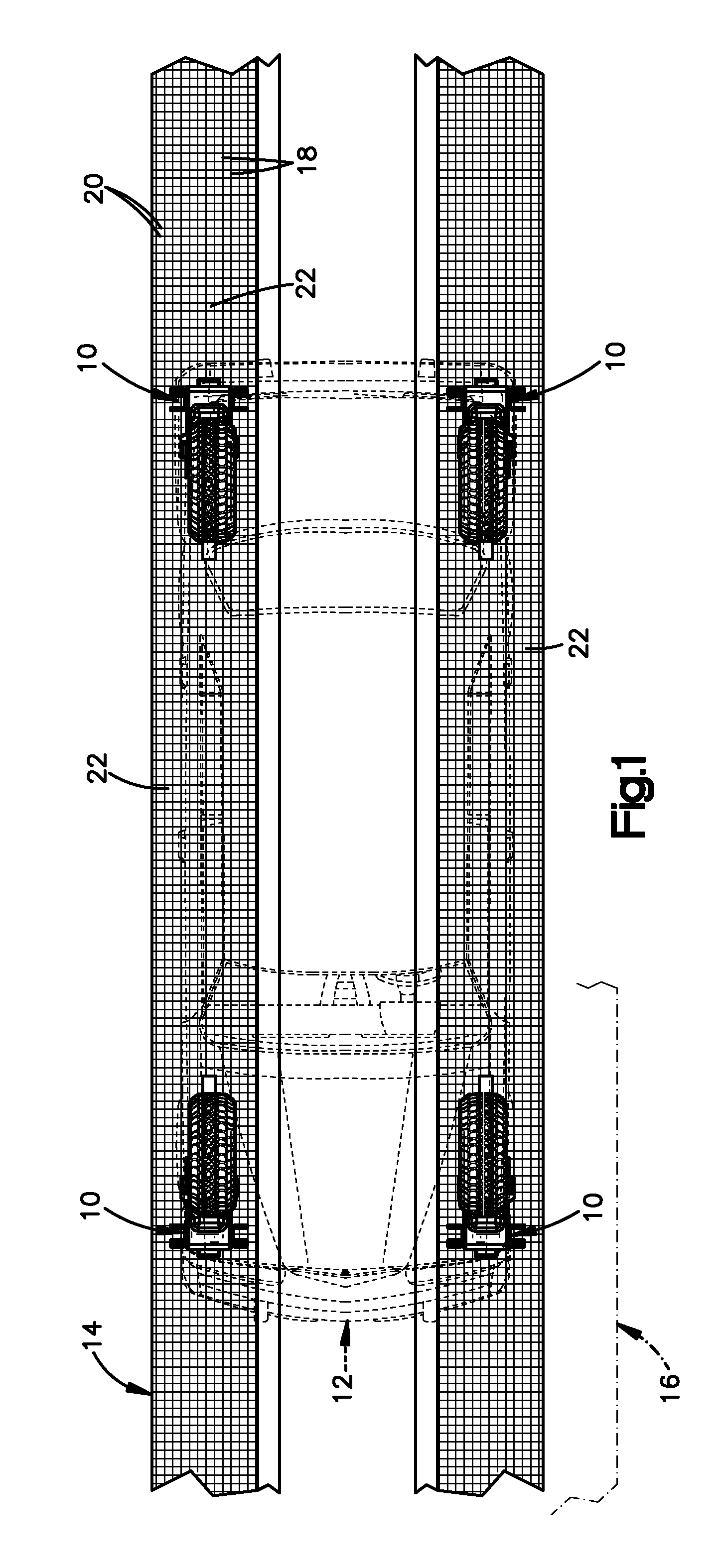
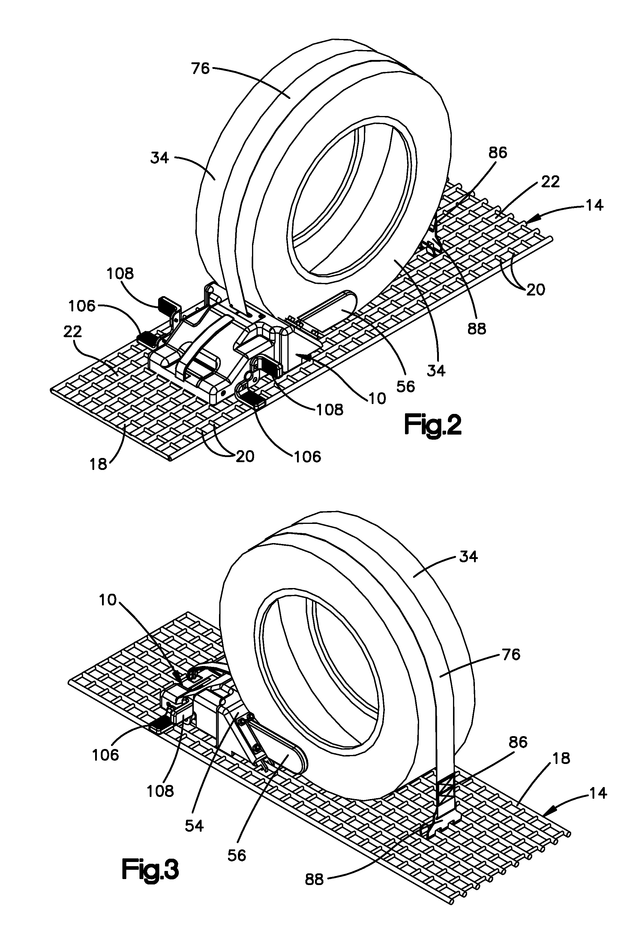
[0025]The present invention relates to a wheel chock and a system including a wheel chock. The invention is applicable to wheel chocks of varying different constructions. As representative of the invention, FIG. 1 illustrates the use of one or more wheel chocks 10 in positioning of a vehicle 12, for example a car, on a grating 14 of a railroad car 16. The grating 14 has longitudinally extending wires 18 and transversely extending cross wires 20 that together define a plurality of square openings 22 in the grating. The front of the car 12 is to the left as viewed in FIG. 1. Four wheel chocks 10 of the present invention are shown holding the car 12 in place on the grating 14, one at each wheel of the car. The two front chocks 10 are positioned adjacent to the front tires to resist movement of the vehicle 12 relative to the grating 14, as described below; the two rear chocks are positioned adjacent to the rear tires to resist movement of the vehicle relative to the grating, as describe...


PUM


Abstract

A wheel chock for restraining movement of a vehicle tire on a supporting grating during transit includes a base, a grate lock mechanism for locking the base to the grating, and a ramp on the base for engagement with a circumference of a vehicle tire. A strap connected with the base is extensible around the vehicle tire to help restrain movement of the tire on the grating. The chock includes a retractor for retracting the strap and for taking up slack that forms in the strap during transit.

Description

RELATED APPLICATIONS[0001]This application claims the benefit under 35 U.S.C. 119(e) of U.S. Provisional Application No. 60 / 952,981 filed Jul. 31, 2007; and of U.S. Provisional Application No. 60 / 968,595, filed Aug. 29, 2007; and of U.S. Provisional Application No. 61 / 065,180 filed Feb. 8, 2008. The disclosures of all of these applications are incorporated by reference.BACKGROUND OF THE INVENTION[0002]The invention relates to a wheel chock, used for example in helping to hold an automobile in position in a railroad car during transportation of the automobile by train (in transit). The invention also relates to a wall mount for a wheel chock, and to a system that includes both the wall mount and the wheel chock.[0003]U.S. Pat. Nos. 5,312,213 and 5,302,063 disclose a wheel chock system for such an application. The system resists fore-and-aft vehicle movement with angled ramps, and also resists lateral vehicle movement, but does not prevent upward movement of the vehicle. Thus, when a ...

Claims


Application Information

Patent Timeline
IPC IPC(8): B60T3/00
CPCB60T3/00
Inventor POWERS, JOSEPH R.WIATRAK, THOMAS R.DIAMOND, FREDERICK J.
Owner MIDWEST PRECISION PRODS
Why Eureka
Try Eureka