Belt transmission device

Inactive Publication Date: 2009-02-05
BANDO CHEM IND LTD
View PDF39 Cites 1 Cited by
  • Summary
  • Abstract
  • Description
  • Claims
  • Application Information

AI Technical Summary

Benefits of technology

[0017]According to the belt drive system of the first aspect of the invention, the load length rate tp is used as an index indicating the surface roughness of the groove surface of the V-pulley and the groove surface is configured to satisfy a particular relation. Therefore, the microscopic contact area between the groove surface of the V-pulley and the side faces of the V-belt can be s

Problems solved by technology

However, when the surface roughness of the groove surface of the V-pulley is evaluated in terms of arithmetic mean roughness Ra as in Patent Document 1, this evaluation reflects the heights of microscopic hills on the groove surface but does not accurately reflect the shapes of the hills.
This increases the frictional resistance of the V

Method used


Image

  • Belt transmission device
  • Belt transmission device
  • Belt transmission device

Examples


Example

EXPLANATION OF REFERENCE NUMERALS

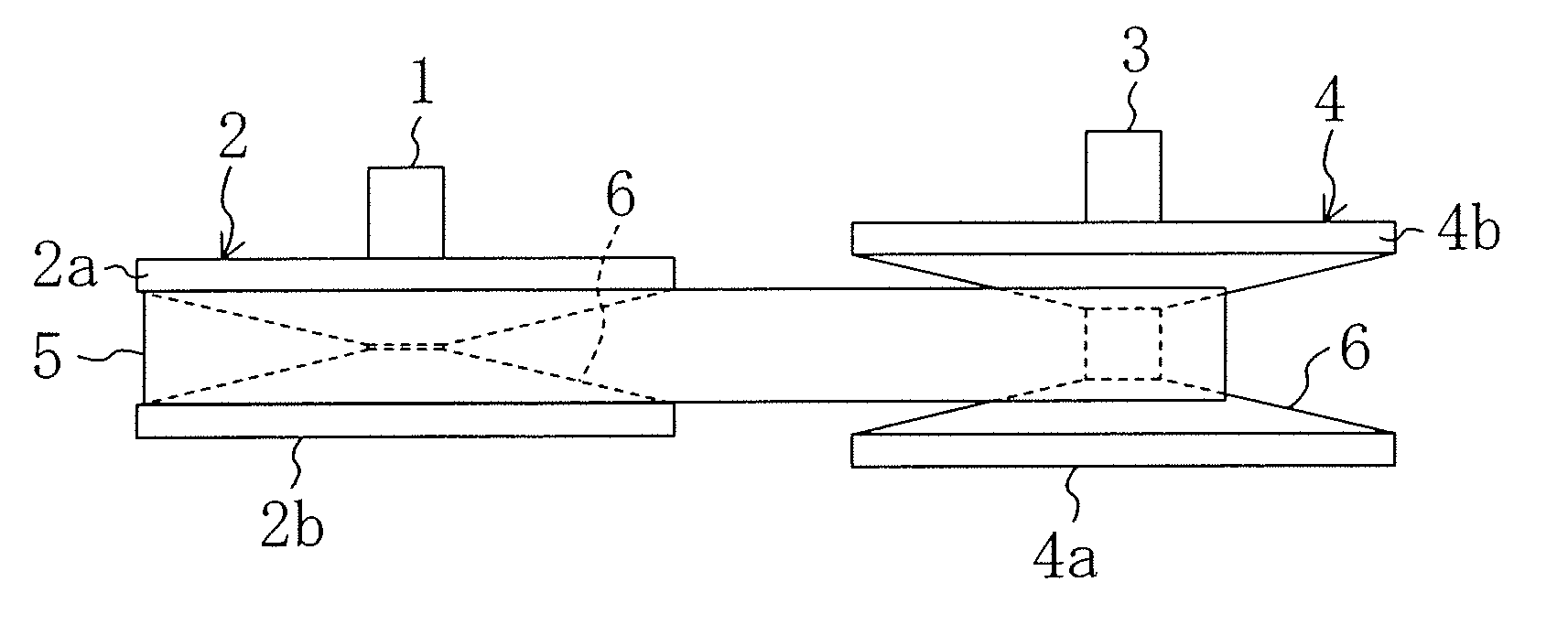
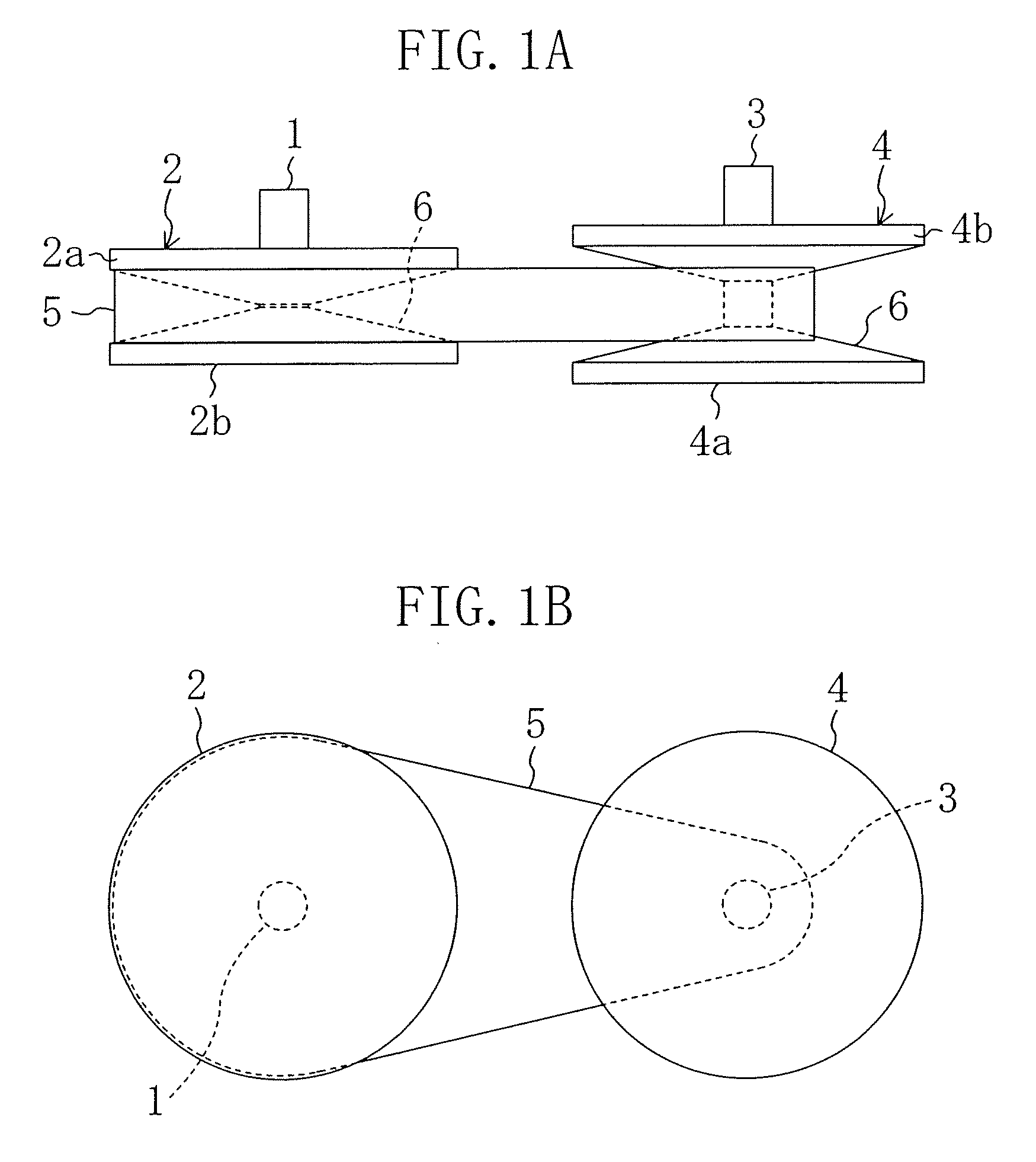
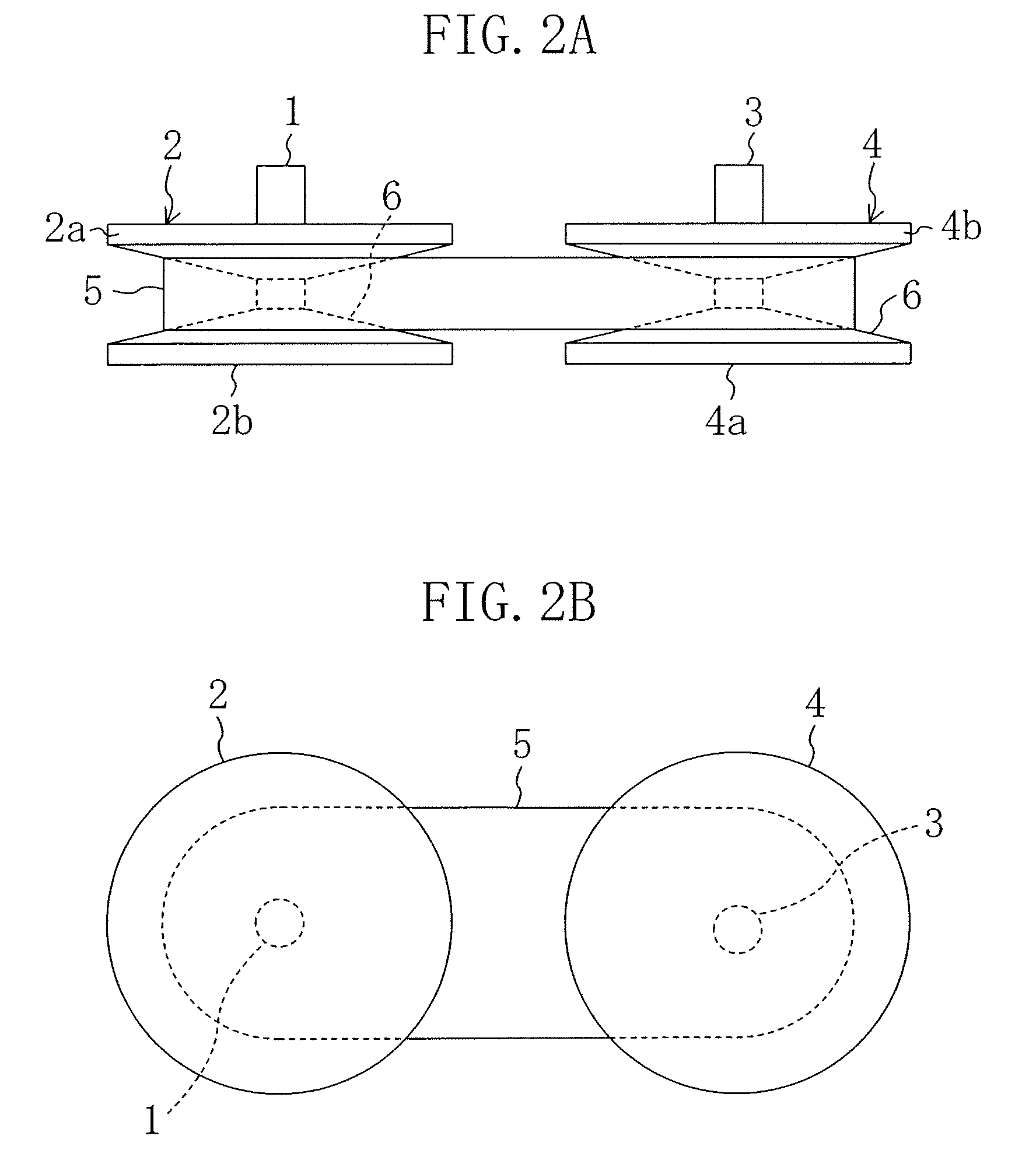
[0030]1 drive rotational shaft[0031]2 drive pulley (V-pulley)[0032]3 driven rotational shaft[0033]4 driven pulley (V-pulley)[0034]5 heavy-duty drive V-belt (drive V-belt)[0035]6 belt groove (groove)[0036]7 block[0037]8 tension member

BEST MODE FOR CARRYING OUT THE INVENTION

[0038]Hereinafter, an embodiment of the present invention will be described with reference to the drawings. The description of the following preferred embodiment is merely illustrative in nature and is not intended to limit the scope, applications and use of the invention.

[0039]FIGS. 1 to 3 show a belt drive system according to an embodiment of the present invention, wherein reference numeral 1 denotes a drive rotational shaft and reference numeral 3 denotes a driven rotational shaft. Both the rotational shafts 1 and 3 are disposed in parallel to each other.

[0040]Disposed on the drive rotational shaft 1 is a drive pulley 2 (V-pulley) formed of a variable speed pulley. The drive pull...


PUM


Abstract

A belt drive system including an assembly of a heavy-duty drive V-belt 5 and pulleys 2 and 4 reduces noise generating owing to belt travel while ensuring the durability of the pulleys 2 and 4. The surfaces of belt grooves 6 in the V-pulleys 2 and 4 are micro-blasted or burnished so that their surface roughness satisfies the relational expression y≦−0.9×tp+100, where tp is the load length rate at a given position of a roughness curve indicating the surface features of the groove surfaces in the V-pulleys 2 and 4 and y is the variable (the degree of height) indicating by percentage the ratio of the height from the lowest valley having a maximum depth to the given position to a maximum height Ry.

Description

TECHNICAL FIELD[0001]This invention relates to belt drive systems with a drive V-belt and particularly relates to the field of technology of reducing noise generating owing to belt travel.BACKGROUND ART[0002]Belt drive systems transmit power via a V-belt by wrapping the V-belt around a V-pulley and frictionally engaging them. There is known a V-belt for such a belt drive system that has a structure in which a large number of blocks are fitted on a pair of tension members. When the V-belt has such a structure, a problem arises that noise during belt travel is relatively large. Specifically, when the V-belt moves into and away from the V-pulley, each block of the V-belt comes into contact with the surface of the V-pulley to produce an impact sound. On the other hand, when each block disengages from the V-pulley, it produces a sticking sound.[0003]Known structures for reducing such noise during belt travel include a structure in which the surface roughness of the groove surface of the ...

Claims


Application Information

Patent Timeline
IPC IPC(8): F16H55/56
CPCF16G5/16F16G5/166F16H55/56F16H55/49F16H9/18
Inventor SAKANAKA, HIROYUKITAKAHASHI, MITSUHIKO
Owner BANDO CHEM IND LTD
Why Eureka
Try Eureka