Aircraft turbine with counter-rotating propellers

Active Publication Date: 2020-01-16
ROLLS ROYCE DEUT LTD & CO KG
View PDF0 Cites 0 Cited by
  • Summary
  • Abstract
  • Description
  • Claims
  • Application Information

AI Technical Summary

Benefits of technology

[0008]Electric drives are significantly quieter than internal combustion drives, with the r

Problems solved by technology

In a simple propeller arrangement, a swirl is imparted to the air that flows through the propeller, that reduces the effi

Method used


Image

  • Aircraft turbine with counter-rotating propellers
  • Aircraft turbine with counter-rotating propellers

Examples


Example

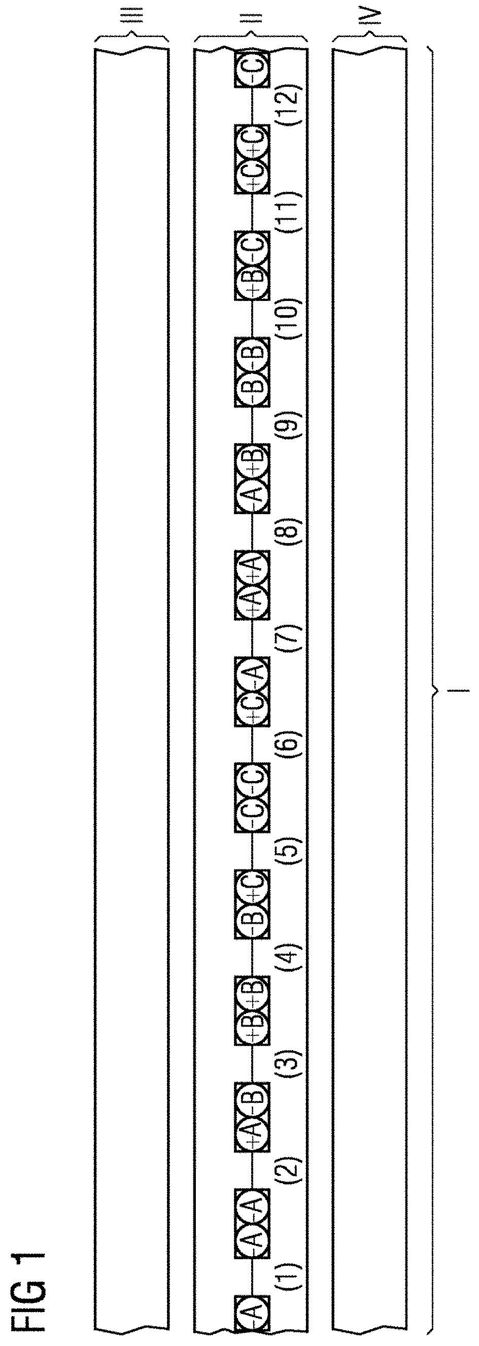
[0016]FIG. 1 depicts a motor module 1, including of a belt winding in the stator II and 10 or 14 poles (tooth coils) in each rotor component III or IV. The portion of the stator II depicted has 12 tooth coils that are arranged on a magnetically and electrically non-conductive support. The rotor component III is configured as an external rotor with, for example, 2P=10 poles (tooth coils) and the rotor component IV is configured as an internal rotor with, for example, 2P=14 poles (tooth coils).

[0017]The motor module I refers to the magnetically smallest unit of an electric motor. The motor module I includes a belt winding and rotor arrangements that include numbers of poles that correspond to the belt winding. An electric motor includes at least one motor module I. The electric motor may, however, also have as many motor modules I as are desired that are electromagnetically symmetrical with respect to one another.

[0018]The proposed permanently excited synchronous motor includes a rota...


PUM


Abstract

The invention relates to an aircraft turbine having counter-rotating propellers and a primary drive, the noise development of which is significantly reduced with respect to aircraft turbines which have a primary drive based on the internal combustion principle. The invention relates to an aircraft turbine having counter-rotating propellers and a primary drive, the primary drive of which is based on the electric drive principle.

Description

CROSS REFERENCE TO RELATED APPLICATIONS[0001]This present patent document is a § 371 nationalization of PCT Application Serial Number PCT / EP2016 / 072683, filed Sep. 23, 2016, designating the United States, which is hereby incorporated in its entirety by reference.FIELD[0002]Embodiments relate to aircraft turbines with counter-rotating propellers.BACKGROUND[0003]Aircraft turbines with counter-rotating propellers are known, the primary drive of which is based on the internal combustion principle.[0004]In a simple propeller arrangement, a swirl is imparted to the air that flows through the propeller, that reduces the efficiency of the propeller. A second counter-rotating propeller attached behind the first propeller reduces this swirl and consequently increases the efficiency of the propeller. However, significant noise generation is entailed by the principle of counter-rotating propellers.SUMMARY AND DESCRIPTION[0005]The scope of the present invention is defined solely by the appended ...

Claims


Application Information

Patent Timeline
IPC IPC(8): B64D35/06B64D35/02H02K16/02
CPCB64D35/06B64D35/02H02K16/02B64C11/48B64D27/24F02K5/00Y02T50/60H02K16/00
Inventor DORFNER, MATTHIASPETERMAIER, KORBINIAN
Owner ROLLS ROYCE DEUT LTD & CO KG
Why Eureka
Try Eureka