Arrangement for Detecting a Crash

a technology for detecting and detecting vehicles, applied in the direction of pedestrian/occupant safety arrangements, instruments, tractors, etc., can solve the problems of not being desirable to trigger the safety device, affecting the safety of vehicles, and losing the benefit of the safety devi

Active Publication Date: 2009-02-05
VEONEER PASSIVE CO AB
View PDF7 Cites 29 Cited by
  • Summary
  • Abstract
  • Description
  • Claims
  • Application Information

AI Technical Summary

Problems solved by technology

If the actuation of the safety device is not triggered within an appropriately short period of time, the benefit of the safety device may be lost and the actuation thereof may be positively harmful to a vehicle occupant.
However, it may not be desirable to trigger the safety device as a result of the low speed crash represented by the second curves a2 and Δv2, as it is unlikely that an occupant will need the protection provided by the safety device since the forces arising from the low speed crash are likely to be minimal.
Unfortunately, as can be seen from FIGS. 1 and 2, the acceleration in a 30 ms time period following the moment at which the acceleration rises above the threshold is largely dependent on the stiffness of parts of the vehicle, and is not heavily dependent upon the severity of the impact.
In a severe impact, such as a high speed crash, the acceleration will continue to rise after the 30 ms interval has passed (following a short “plateau” phase) but, as discussed above, it is not desirable to wait longer than the 30 ms interval this before a decision must be taken as to whether to actuate the safety device.
Thus, selecting a low value for the predetermined threshold ΔvT can result in the safety device being unnecessarily actuated in the event of a low speed crash.
However, the raising of the predetermined threshold ΔvT means that the length of time until which the change in velocity Δv takes to reach the threshold is increased, thus increasing the length of time after which the crash occurs when the safety device is actuated.
Therefore, the need arises for a crash detection arrangement which can actuate a safety device swiftly to protect an occupant of a vehicle during a high speed crash, but which will not actuate the safety device unnecessarily in response to a relatively low speed crash.

Method used


Image

  • Arrangement for Detecting a Crash
  • Arrangement for Detecting a Crash
  • Arrangement for Detecting a Crash

Examples


Embodiment Construction

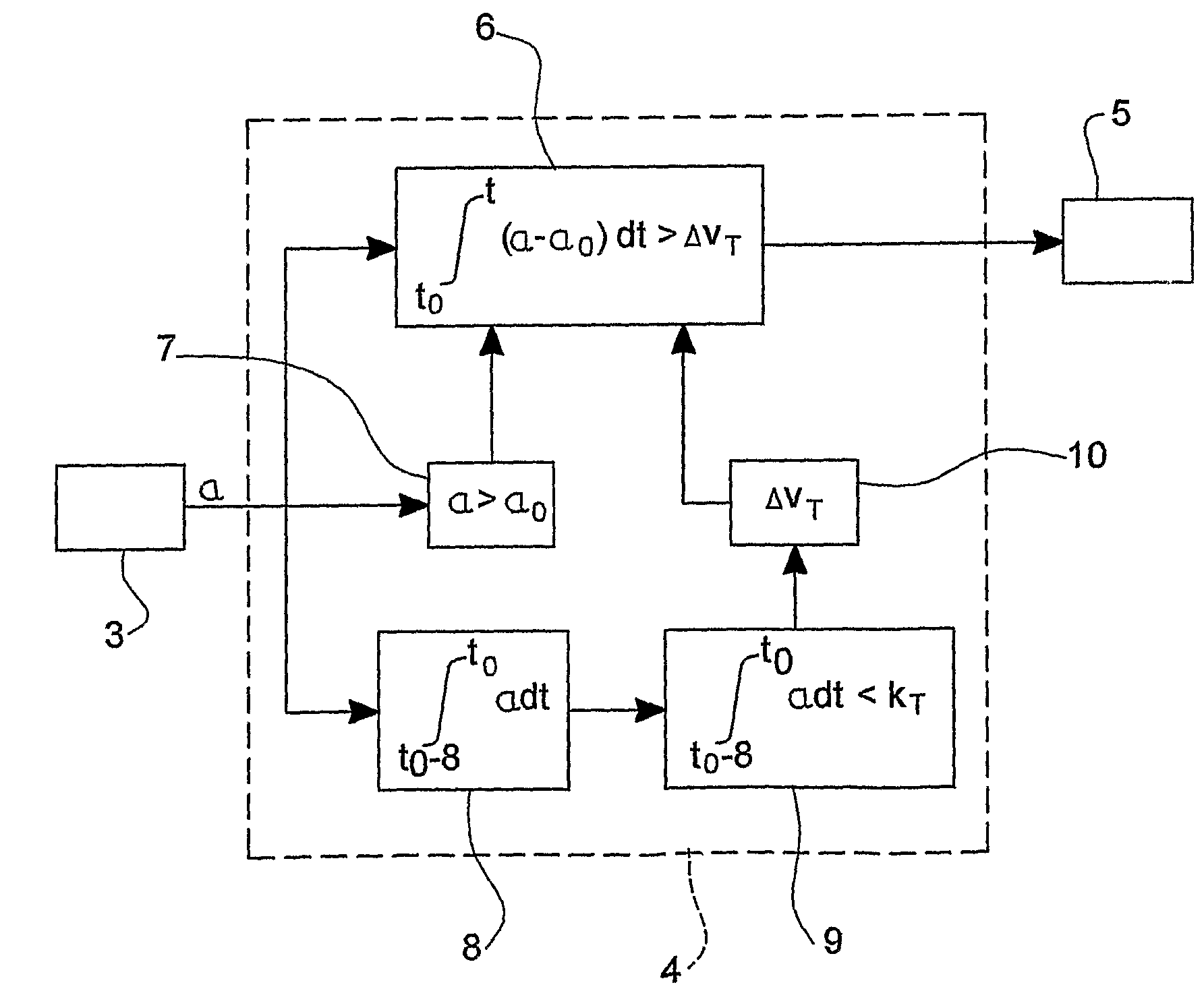
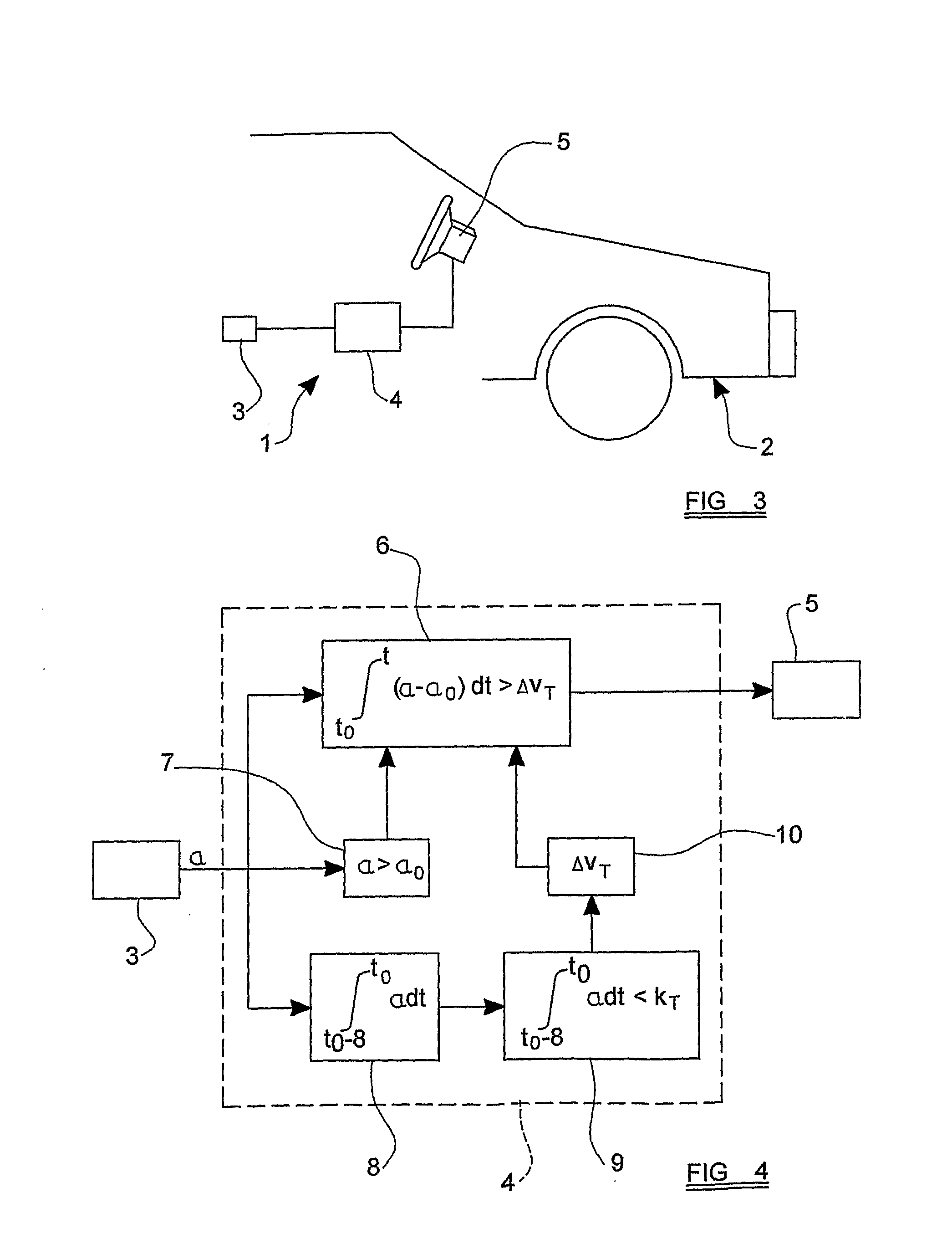
[0051]Referring now to FIG. 3, a crash detection arrangement 1 embodying the present invention is installed in a motor vehicle 2 for detecting a crash situation. The arrangement 1 incorporates an accelerometer 3 which is configured to measure the acceleration of the vehicle 2. The accelerometer 3 is connected to supply a signal which is indicative of the acceleration of the vehicle 2 to a control unit 4. The control unit 4 processes the signal from the accelerometer 3 (in a manner which will be discussed below) to determine whether a crash situation is occurring. The control unit 4 is connected to a safety device 5 to provide a control to the safety device 5 in the event that a crash situation is detected, to control the operation of the safety device 5 to protect an occupant of the vehicle. The safety device 5 shown here is in the form of a front air-bag unit which may be actuated to inflate an air-bag, but it is to be appreciated that the safety device 5 may be any other type of s...


PUM


Abstract

A crash detection arrangement, to be installed in a motor vehicle, for detecting a crash and providing a control signal for controlling a safety device in the event that a crash is detected, the arrangement comprising an accelerometer and a control unit, the accelerometer being arranged to supply a signal to the control unit which is indicative of the acceleration of the vehicle, the control unit being adapted to: calculate a classification parameter based on the value of the signal from the accelerometer during a classification time period, which includes an interval of time before an initiation criterion was fulfilled; modify a crash evaluation algorithm in dependence upon the classification parameter; and perform the crash evaluation algorithm upon fulfillment of the initiation criterion to produce the control signal.

Description

CROSS REFERENCE TO RELATED APPLICATIONS[0001]This application claims priority to GB 0524887.7, filed Dec. 6, 2005 and PCT / SE2006 / 001339, filed Nov. 28, 2006.FIELD OF THE INVENTION[0002]The present invention relates to an arrangement for detecting a crash, and more particularly relates to an arrangement, to be installed in a motor vehicle, for detecting a crash and evaluating the severity of the crash, and for providing a signal to actuate a safety device to protect an occupant of the vehicle in the event that a crash situation occurs.BACKGROUND OF THE INVENTION[0003]Conventional crash detection arrangements typically comprise a crash sensor and a control unit. The crash sensor is usually an accelerometer which is connected to a processor within the control unit to provide a signal to the processor which is indicative of the acceleration applied to the vehicle, for instance by forces arising during a crash situation. The control unit is usually provided with a first comparator which ...

Claims


Application Information

Patent Timeline
Patent Type & Authority Applications(United States)
IPC IPC(8): B60R21/0132
CPCB60R21/0132G08B31/00
Inventor ERB, YANNICK
Owner VEONEER PASSIVE CO AB
Why Eureka
Try Eureka