Golf course bunker boundary protection system

a bunker and boundary protection technology, applied in the field of golf course bunker boundary protection system, can solve the problems of affecting the maintenance difficulty of the golf course hole and bunker, changing shape, affecting the size of the bunker, etc., and achieve the effect of preventing the alteration of the bunker's siz

Inactive Publication Date: 2009-02-12
INDIAN VALLEY INDS
View PDF17 Cites 17 Cited by
  • Summary
  • Abstract
  • Description
  • Claims
  • Application Information

AI Technical Summary

Benefits of technology

[0007]Accordingly, an object of the invention is to provide a bunker boundary protection system for preventing the alteration of the bunker's size.

Problems solved by technology

Bunkers on golf courses, over time, change shape due to erosion from grass cutting machines and water.
This tends to be a problem because the size of the bunker changes and affects the difficulty of the golf course hole and bunker maintenance.
In some instances, conventional bunkers erode after prolonged periods of water hitting the surface of the bunker.
These systems can also resist bunker edge displacement from grass cutting but will eventually be displaced approximately nine months after installation due to the residual effects of water in the bunker.
The water causes the system to recede from the edge of the sand and lose its vertical position, thus still changing the shape of the bunker.

Method used


Image

  • Golf course bunker boundary protection system
  • Golf course bunker boundary protection system
  • Golf course bunker boundary protection system

Examples


Embodiment Construction

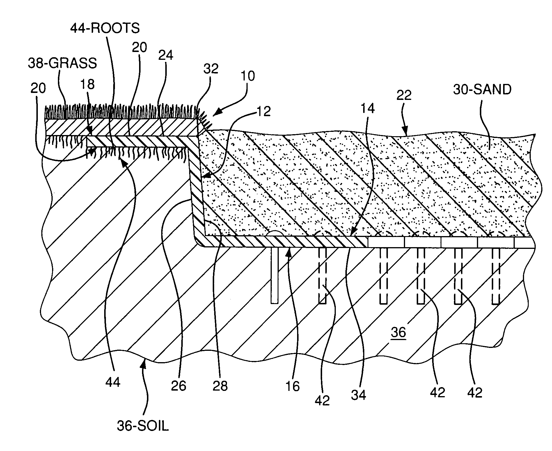
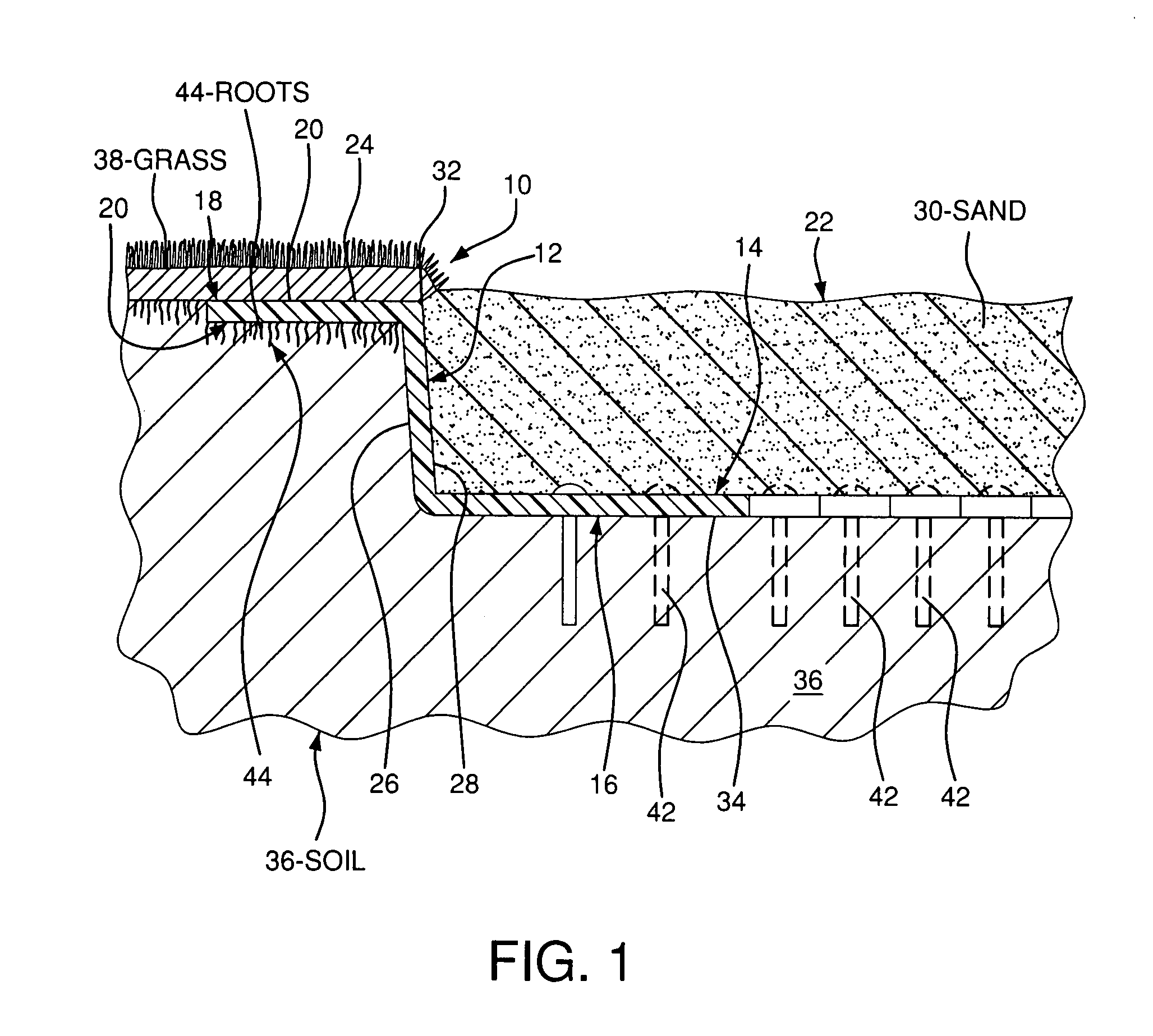
[0025]Turning to FIGS. 1-4, a bunker boundary protection system 10 is shown installed into a sand bunker 22 on a golf course for stabilizing and maintaining the structure of the bunker over time. The bunker boundary protection system 10 comprises a central section 12, a lower section 14 having a plurality of lower anchors 16 each coupled to the central section 12, and an upper section 18 having a plurality of upper anchors 20 each coupled to the central section 12. The bunker boundary protection system 10 is placed into a bunker 22 such that the central section 12 is adjacent to the wall 24 of the bunker 22, upper anchors 20 are below the grass 38, and lower anchors 16 are between the sand 30 and soil 36.

[0026]Preferably, the bunker boundary protection system 10 includes the central section 12, upper anchors 20, and lower anchors 16 integrally formed as one piece of material. The material is a sheet of thin, flexible polymeric material, such as linear low polyethylene, preferably 1 / ...


PUM


Abstract

The golf course bunker boundary protection system includes a central section located adjacent to the wall of a bunker, a plurality of lower anchors coupled to the central section and located below the sand in the bunker and above the soil in the bunker below the sand, and a plurality of upper anchors coupled to the central section and located between the grass surrounding the bunker and the soil. The upper anchors include a means for attaching the upper anchors to the grass, and the lower anchors include a means for securing the lower anchors to the soil, such as staples, pins, or nails. Advantageously, the upper and lower anchors and the central section are formed of one piece of thin, flexible polymeric material.

Description

FIELD OF THE INVENTION[0001]The present invention relates to a golf course bunker boundary protection system advantageously formed of a thin polymeric sheet and having a central section located adjacent to the wall of the bunker, lower anchors and upper anchors. The lower anchors are coupled to the central section and located between the sand in the bunker and the soil below the sand. The lower anchors include a means for securing the lower anchors to the soil. The upper anchors are coupled to the central section and located below the grass surrounding the bunker. The upper anchors include a means for attaching the anchors to the grass surrounding the bunker.BACKGROUND OF THE INVENTION[0002]Bunkers on golf courses, over time, change shape due to erosion from grass cutting machines and water. Without a protective layer, the edge of the bunker where the grass meets the sand could ultimately creep back five to ten feet over five years. This tends to be a problem because the size of the...

Claims


Application Information

Patent Timeline
Patent Type & Authority Applications(United States)
IPC IPC(8): A01G1/08A01G9/28
CPCA01G1/08A01G9/28
Inventor ROZEN, WAYNE A.
Owner INDIAN VALLEY INDS
Why Eureka
Try Eureka