Electric drive mower with trailed auxiliary power source

a technology of electric drive and auxiliary power source, which is applied in the direction of electric propulsion mounting, battery/fuel cell control arrangement, propulsion by batteries/cells, etc., can solve the problems of significant damage to golf greens or fairways, difficult and impractical to mow large areas, and the range of battery packs carried by the present mower remains inherently limited by the power capabilities of conventional batteries

Inactive Publication Date: 2005-09-06
TEXTRON INNOVATIONS
View PDF32 Cites 51 Cited by
  • Summary
  • Abstract
  • Description
  • Claims
  • Application Information

AI Technical Summary

Benefits of technology

[0016]In light of the foregoing problems and in order to fulfill one or more of the foregoing objects, there is provided, in accordance with a first aspect of the present invention, a self-propelled riding mower having a frame supported on a plurality of ground engaging wheels. The frame supports an electrical power source for supplying electrical energy to the mower and further supports a plurality of reel type lawn mowers which are movable between a raised position and a lowered position, in accordance with operation and non-operation, respectively. The reel mowers are driven by electrical motors which receive electrical power from the power source, which may be, for example, a battery pack, a motor / generator set, or a fuel cell. A prime mover having an electric motor is also supplied with electrical energy from the power source, where the prime mover is adapted to provide torque to one of the ground engaging wheels upon which the frame is supported.

Problems solved by technology

As is known, hydraulic oil leaks in conventional hydraulically-driven and hydraulically-powered turf care equipment can significantly damage a golf green or fairway if undetected by the mower operator.
While the disclosed all-electric greens mower is quite satisfactory and much appreciated, it is difficult and impractical to mow large areas, such as fairways or parks with that style of mower, even when appropriate reel-style mowing heads are installed.
The range of the battery packs carried by the present mowers remain inherently limited by the power capabilities of conventional batteries.
One challenge presently faced by many golf course operators is that municipalities and communities, especially those which have residential homes bordering the golf courses, restrict by ordinance the hours during which the fairways and greens may be mowed.
Golf course operators, on the other hand, dislike mowing their courses during peak golfing times, between 7:00 a.m. and 7:00 p.m. during the golfing season.
This challenge presents particular difficulties for golf course owners whose courses are continuously busy, and usually have a waiting list of people seeking tee times.
Unfortunately, the battery range of a riding electric mower with one bank of batteries (even though the battery weight is in excess of 400 pounds) is limited.
Battery-powered commercial mowers, therefore, remain impractical for mowing large areas due to the typically extensive recharge times required to fully recharge the battery and the undesirable need to interrupt the mowing process (which the golfers wish to have completed as expeditiously as possible) while the batteries are re-charging.

Method used


Image

  • Electric drive mower with trailed auxiliary power source
  • Electric drive mower with trailed auxiliary power source
  • Electric drive mower with trailed auxiliary power source

Examples


first embodiment

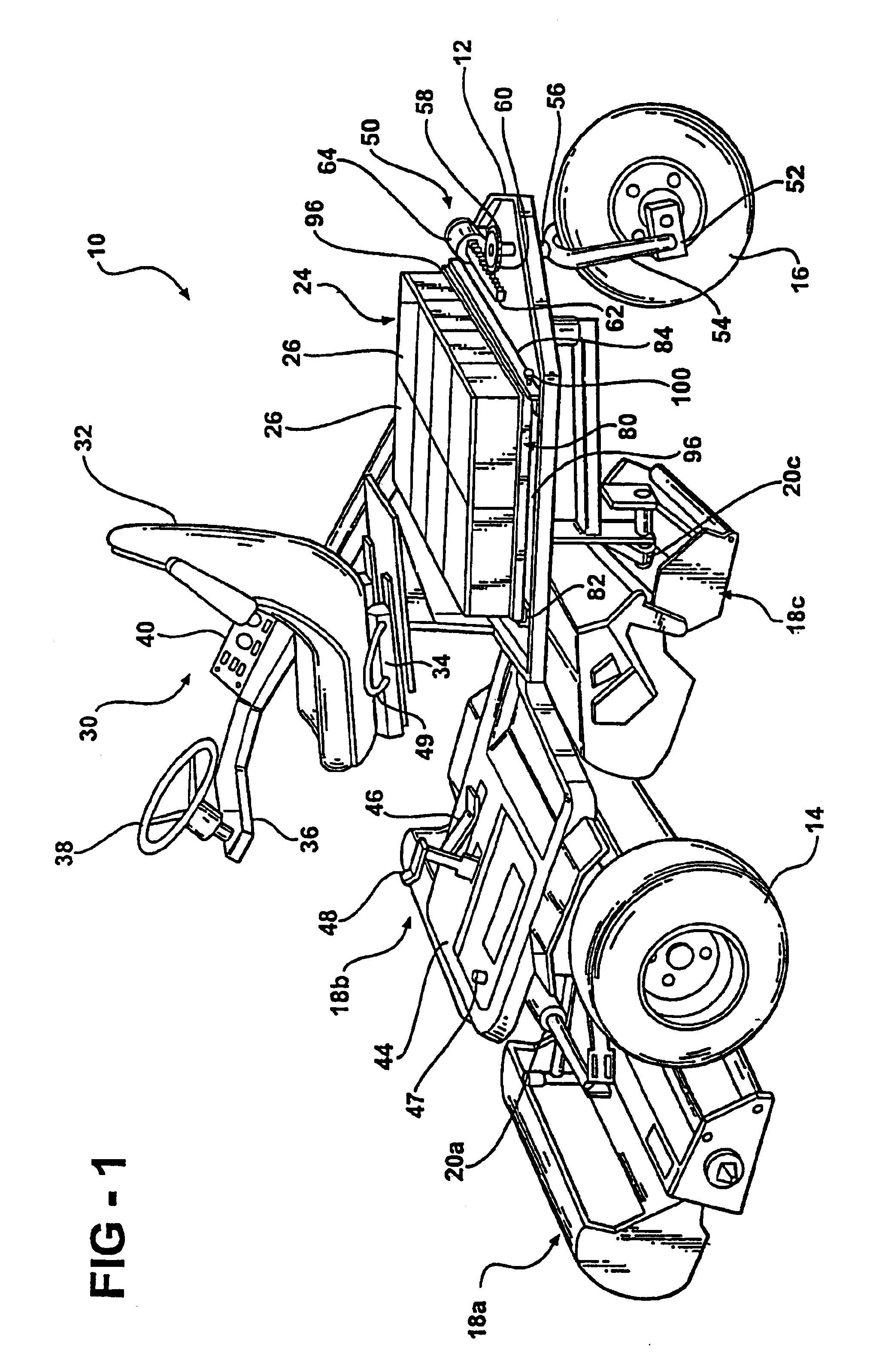
[0047]FIGS. 1 and 3 depict the present invention in which the power source 24 engages a guided, rolling platform to facilitate the interchange of power sources 24. Referring to FIGS. 1 and 3, a roller tray assembly 80 is mounted to the frame 12 of the mower 10. The roller tray assembly includes an angled channel 82 mounted forward of the power source 24 so that the power source 24 is seated within the angular portion of the angled channel 82. The angled channel 82 provides a forward retainer and guide for the power source 24. A second angled channel 84 is mounted rearward of the power source 24 so that the power source is seated within the angled portion of the angled channel 84. The angled channel 84 both guides and retains the power source 24, and in particular, provides a rear retainer for the power source 24. A plurality of rollers 86 connect the angled channels 82 and 84 to facilitate the interchange of the power source 24. The rollers 86 include substantially rigid rods 88 ext...

second embodiment

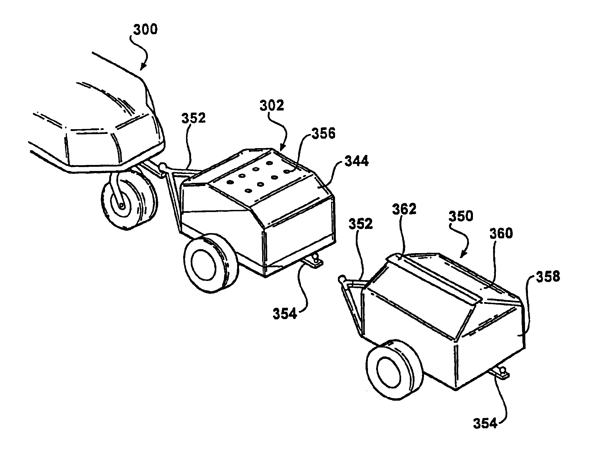
[0055]In a trailer adapted for direct interchange, FIGS. 9 and 10 depict a trailer 170 for direct exchange of a discharged power source 112 with a charged power source 172. Note that like reference numerals from FIGS. 7 and 8 will be used to reference similar elements in FIGS. 9 and 10. FIG. 9 depicts a rear view of the mower 10 with the trailer 170 arranged to the left side of the mower and supporting a charged power source 172 for replacing the discharged power source 112. In operation, a temporary stand 174 is erected on a side of the mower 10 opposite the trailer 170. Temporary stand 174 includes a pair of legs 176 which support the combined weight of the stand 174 and the power source disposed thereon. The discharged power source 112 is removed from the mower 10 by sliding it toward the right of the mower onto temporary stand 174. Once discharged power source 112 has been positioned on temporary stand 174, charged power source 172 may then be moved from the trailer 170 onto the...


PUM


Abstract

Provided is an all-electric riding greens mower. The mower includes a frame which is supported for movement upon a plurality of ground engaging wheels and upon which are supported a modularly interchangeable power source and a plurality of reel lawn mowers. An electric motor provides driving torque to enable movement of the mower between and over golf course greens or other surfaces to be mowed, electric motors provide driving torque for each of the reel lawn mowers. The interchangeable power source provides electrical energy for driving the electric motors, including the primary mover and the electrical motors for the reel type lawn mowers. The modularly interchangeable power sources may comprise a bank of batteries, a motor/generator set, a fuel cell, or a combination of these. The power source may be easily exchanged in the field for another, freshly charged power source. Exchange occurs using either a fixed change stand or a mobile change stand. The change stands are configured to facilitate exchange by reducing friction caused by the generally weighty power source. The power source is delivered to the fixed stand on towable trailers.

Description

CROSS-REFERENCE TO RELATED APPLICATIONS[0001]This application is a divisional of U.S. patent application Ser. No. 10 / 268,358 filed Oct. 10, 2002, now U.S. Pat. No. 6,729,114 which is a divisional of U.S. patent application Ser. No. 09 / 489,124 filed on Jan. 21, 2000, now U.S. Pat. No. 6,571,542 issued Jun. 3, 2003, which claims the benefit of U.S. Provisional Patent Application No. 60 / 126,153 filed on Mar. 25, 1999. The disclosures of the above applications are incorporated herein by reference.FIELD OF THE INVENTION[0002]The present invention generally relates to electrically-powered riding mowers for use on golf courses and other large grounds, and more particularly relates to electrically-powered riding mowers that utilize modular, interchangeable electrical power sources which may include a bank of batteries, a motor / generator set, a fuel cell or combination thereof, for providing electrical power to the mower.BACKGROUND OF THE INVENTION[0003]The assignee of the present invention ...

Claims


Application Information

Patent Timeline
Patent Type & Authority Patents(United States)
IPC IPC(8): A01D69/00A01D69/02A01D34/03A01D34/58A01D34/78
CPCA01D34/58A01D34/822A01D69/02B60L11/126B60L11/1816B60L11/1822B60L11/1824B60L11/1853B60L11/1864B60L11/1877B60L11/1879B60L15/20A01D34/78Y02T10/7275Y02T10/7077Y02T10/7005Y02T10/7061Y02T10/7072Y02T90/124Y02T90/121Y02T90/14B60L2200/28B60L2200/40B60L2240/423Y02T10/648Y02T10/6217B60L50/62B60L50/64B60L50/66B60L53/80B60L58/18B60L58/21Y02T10/62Y02T10/64Y02T10/70Y02T10/72Y02T90/12
Inventor FILLMAN, ALAN R.SAIIA, ANTHONY J.REIMERS, KIRK W.
Owner TEXTRON INNOVATIONS
Why Eureka
Try Eureka