Oscillating Piston Engine

a piston engine and oscillating piston technology, applied in the direction of arcuate-engagement engines, rotary piston engines, rotary or oscillating piston engines, etc., can solve the problem of increasing design costs

Inactive Publication Date: 2009-02-12
HUETTLIN HERBERT
View PDF10 Cites 11 Cited by
  • Summary
  • Abstract
  • Description
  • Claims
  • Application Information

AI Technical Summary

Benefits of technology

[0009]The invention is based on the object of specifying an oscillating piston engine which breaks with the approach for arranging the pistons of the known oscillating piston engine, and which in this case also allows the gas exchange of the working chambers to be controlled in a simple manner in terms of design.

Problems solved by technology

The actual gas exchange openings, which are associated with the working chambers, are provided with controlled valves, and this increases the design costs.

Method used


Image

  • Oscillating Piston Engine
  • Oscillating Piston Engine
  • Oscillating Piston Engine

Examples


Embodiment Construction

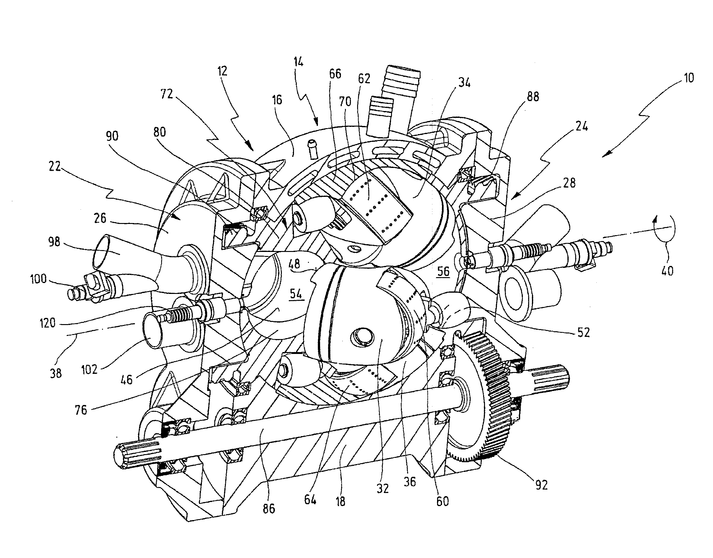
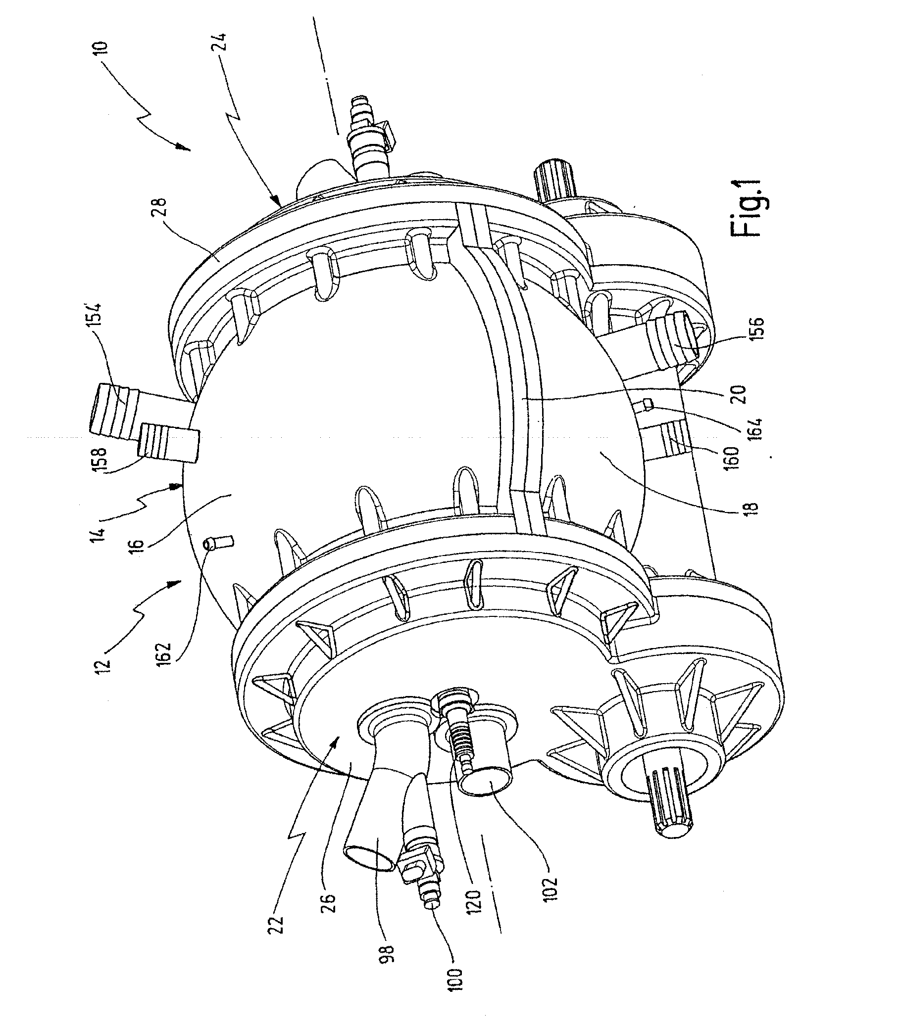
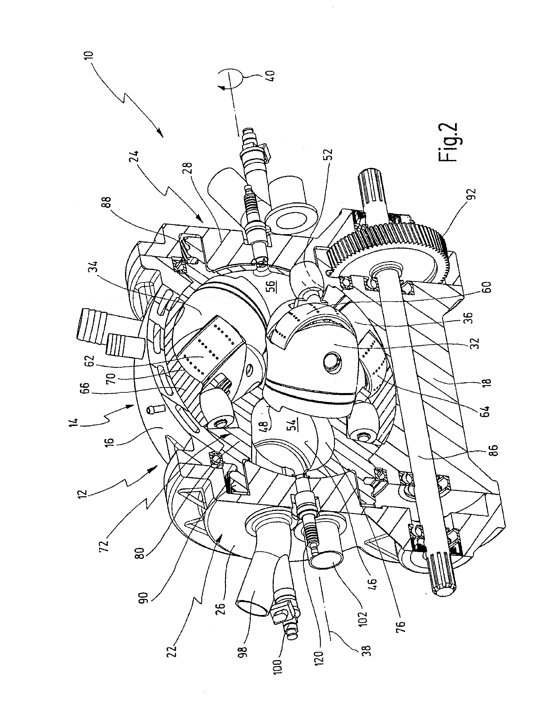
[0049]FIG. 1 to 4 show an oscillating piston engine provided with general reference numeral 10. Further details of the oscillating piston engine 10 are shown in FIG. 5 to 10.

[0050]The oscillating piston engine 10 is generally designed as an internal combustion engine but, modified accordingly, can also be used as a pump or as a compressor.

[0051]The oscillating piston engine 10 has a housing 12 which in FIG. 1 is shown closed. The housing 12 has a central housing portion 14 which is spherical in its formation. The central housing portion 14 is composed of two housing halves 16 and 18 which are joined together via a flange 20.

[0052]The housing 12 also has a first end face 22 and a second end face 24 opposing the first end face 22.

[0053]The first end face 22 is formed by an end-face housing lid 26 and the second end face 24 by an end-face housing lid 28. The housing lids 26 and 28 are connected to the central housing portion 14 or the housing halves 16 and 18 thereof. The housing lids ...


PUM


Abstract

The invention relates to an oscillating piston engine comprising a housing that contains a first and at least a second piston, both of which can rotate about a fixed rotational axis in the housing and which when rotating about said axis execute counter-rotating displacements back and forth about a pivoting axis that runs perpendicular to the rotational axis through the centre of the housing. A working chamber is situated between opposing end faces of the first and at least second piston. The housing is provided with at least one gas exchange opening for admitting or discharging a gas into or from the working chamber. The pistons are arranged in such a way that the rotational axis runs through the working chamber. The pistons are mounted to slide in a piston cage, which is located in the housing, is concentric with the rotational axis, and rotates together with the pistons about said axis. The gas exchange opening is arranged eccentrically in relation to the rotational axis, on one end face of the housing.

Description

CROSS-REFERENCE TO RELATED APPLICATIONS[0001]The present application is a continuation of pending international patent application PCT / EP2007 / 001488 filed on Feb. 21, 2007 which designates the United States, and which claims priority of German patent application no. 10 2006 009 198.1 filed on Feb. 22, 2006.BACKGROUND OF THE INVENTION[0002]The invention generally relates to oscillating piston engines. More specifically, the present invention relates to an oscillating piston engine of the type having a housing in which a first and at least a second piston are arranged which can jointly revolve in the housing about an axis of rotation which is fixed in relation to the housing, and which perform when revolving about the axis of rotation reciprocating pivoting movements in opposite directions relative to one another about a pivot axis running through the center of the housing perpendicularly to the axis of rotation, wherein a working chamber is arranged between mutually facing end surfac...

Claims


Application Information

Patent Timeline
Patent Type & Authority Applications(United States)
IPC IPC(8): F02B53/04F01C9/00F01C1/00
CPCF01C9/005F01C21/104Y02T10/17F02B53/04F01C21/18Y02T10/12
Inventor HUETTLIN, HERBERT
Owner HUETTLIN HERBERT
Why Eureka
Try Eureka