Erectable canopy with reinforced roof structure

a technology of reinforced roof structure and raised roof, which is applied in the direction of connections, building types, constructions, etc., can solve the problems of reducing the service life of the raised roof structure, affecting reducing the service life of the structure, so as to and reduce the impact of the structur

Inactive Publication Date: 2009-02-12
INT E Z UP INC
View PDF99 Cites 1 Cited by
  • Summary
  • Abstract
  • Description
  • Claims
  • Application Information

AI Technical Summary

Benefits of technology

[0007]Briefly, and in general terms, the present invention provides for an improved, lightweight erectable canopy shelter with a reinforced raised roof structure that is strengthened and stabilized to permit the roof structure to remain in a raised configuration in order to provide adequate headroom and adequately shed debris and precipitation, and to resist downward wind pressures on the roof structure.
[0012]In a currently preferred aspect of this embodiment, at least one of the sides is raised, being formed by a pair of first and second link members dimensioned so as to extend above the upper ends of the legs when the shelter is in an extended configuration. In a presently preferred aspect, the inner ends of the first link members are connected together and the inner ends of the second link members are connected together, and the second link members are longer than the first link members on each raised side so as to cause the second link members of the side to extend above the upper ends of the legs when the shelter is in an extended configuration. In a currently preferred embodiment, two opposing sides of the shelter are raised so as to form a gabled configuration of the shelter when the shelter is extended.

Problems solved by technology

However, the sliding coupling of the corner linking rods must slide over a considerable length of the roof rods which can lead to abrasion and wear of the roof rods and eventually interfere with the sliding of the linking rods during setting up and taking down of the structure, without providing any significant reinforcing strength or vertical support of the roof structure when the shelter is fully unfolded and extended.
Lightweight shelters with raised roof structures are particularly useful for holding gatherings in inclement weather, to provide needed headroom and shed precipitation and debris, but raised roof structures can be particularly vulnerable to downward forces placed on a roof structure by strong winds.

Method used


Image

  • Erectable canopy with reinforced roof structure
  • Erectable canopy with reinforced roof structure
  • Erectable canopy with reinforced roof structure

Examples


Embodiment Construction

[0027]As attempts have been made to improve portability and expansion of quickly erectable temporary shelter structures, maximizing extended dimension and minimizing weight, modification of roof structures of such shelters to provide adequate headroom, shed precipitation and debris, and to withstand strong winds under a variety of conditions has become increasingly important.

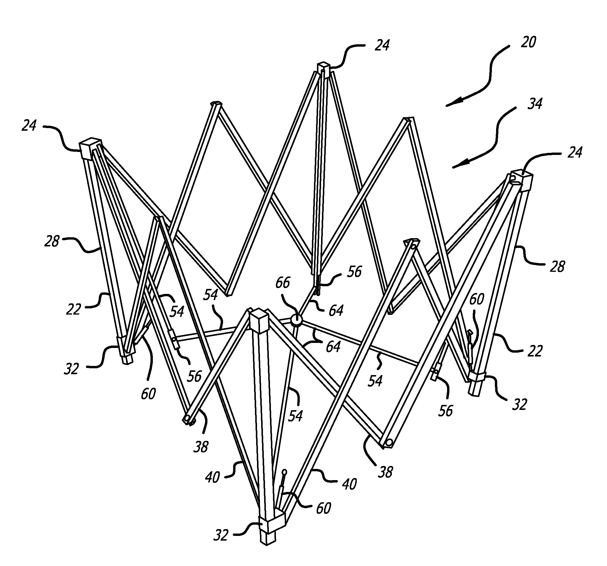
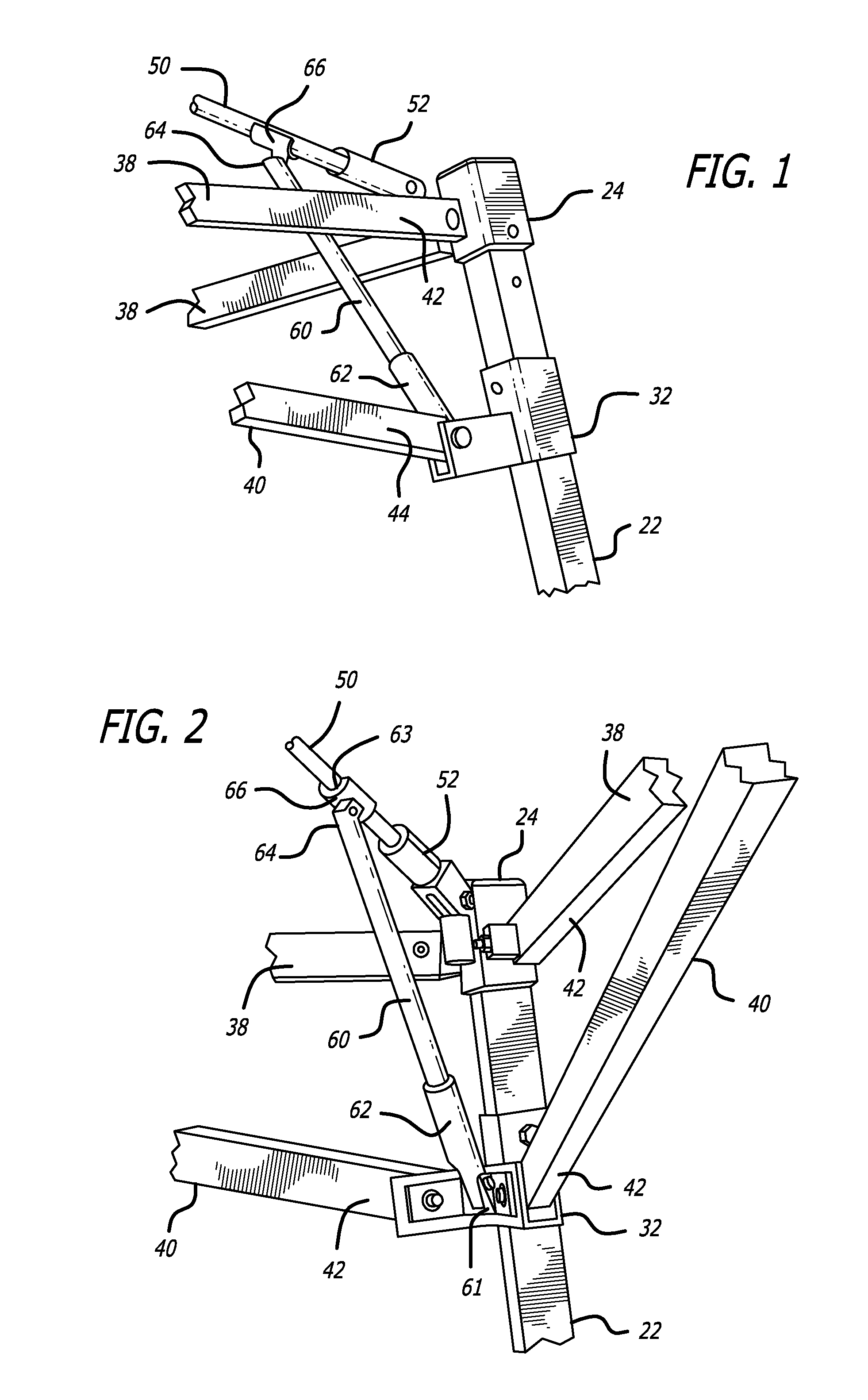
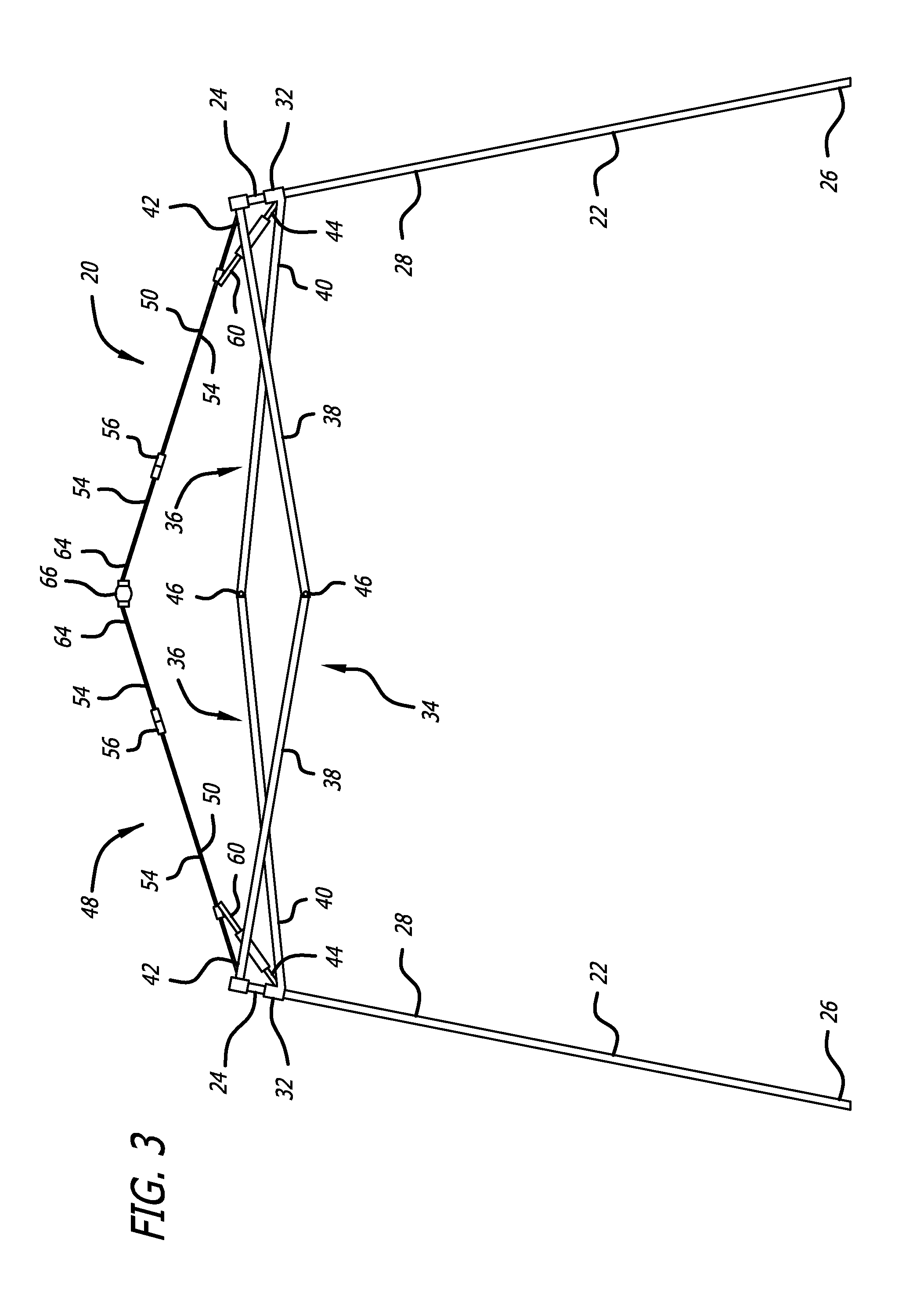
[0028]As is illustrated in the drawings, in a first presently preferred embodiment, the invention provides for a quickly erectable canopy shelter 20 having a plurality of legs 22, each having an upper end 24 and a lower end 26, as shown in FIG. 3. The collapsible shelter preferably has four legs, but can also have three, five, or more legs. Each leg also preferably has an upper section 28 and a telescoping lower section (not shown), with a slider member 32 slidably mounted to the upper section of each of the legs. An extendible perimeter assembly 34 of link members connects adjacent legs together. In a presently...


PUM


Abstract

The lightweight erectable canopy shelters include a plurality of legs connected together by an extendible perimeter assembly of link members. In one embodiment, the roof structure is formed by a pole members pivotally mounted to the upper ends of the legs so as to extend across the shelter, and movable between a lowered position and a raised, upwardly arching position. The pole members are pivotally coupled to a central hub, and each of the pole members comprises pole sections hinged to permit downward folding and upward unfolding until they are fully extended. Corner support strut members are pivotally mounted to the legs, to be rotatable upwardly to engage and support the pole members. In an alternate embodiment, opposing sides of the shelter are connected together by a central assembly of link members, and at least one of the sides of the shelter is raised, being formed by a pair of first and second link members dimensioned so as to extend above the upper ends of the legs when the shelter is in an extended configuration.

Description

CROSS -REFERENCE TO RELATED APPLICATIONS[0001]Continuation of application Ser. No. 11 / 645,206, filed on Dec. 22, 2006, pending, which is a continuation of application Ser. No. 11 / 372,558, filed on Mar. 9, 2006, now U.S. Pat. No. 7,178,542, which is a division of application Ser. No. 11 / 152,867, filed on Jun. 14, 2005, now U.S. Pat. No. 7,051,745, which is a continuation of application Ser. No. 10 / 788,782, filed on Feb. 27, 2004, now U.S. Pat. No. 6,926,021, which is a continuation of application Ser. No. 10 / 337,945, filed on Jan. 6, 2003, now U.S. Pat. No. 6,701,949, which is a continuation of application Ser. No. 10 / 052,292, filed on Jan. 18, 2002, now U.S. Pat. No. 6,502,597, which is a division of application Ser. No. 09 / 490,860, filed on Jan. 24, 2000, now U.S. Pat. No. 6,382,224, which is a continuation in part of application Ser. No. 09 / 277,250, filed on Mar. 26, 1999, now U.S. Pat. No. 6,076,312, and a continuation in part of application Ser. No. 09 / 131,148, filed on Aug. 7, ...

Claims


Application Information

Patent Timeline
Patent Type & Authority Applications(United States)
IPC IPC(8): E04H15/50E04H15/34E04H15/44
CPCY10T403/44E04H15/50E04H15/18
Inventor CARTER
Owner INT E Z UP INC
Why Eureka
Try Eureka