Optical barcodes having spatially phase shifted clock and reference tracks

a phase shift clock and optical barcode technology, applied in the field of barcode readers, can solve the problems of new scanning attempt, inability to meet the demands of speed constancy and unidirectionality, and all previously used barcodes assume precise unidirectionality, etc., to achieve sufficient headroom, reduce the effect of angle-offset errors and greater module heigh

Active Publication Date: 2016-11-22
ROCHE DIABETES CARE INC
View PDF20 Cites 2 Cited by
  • Summary
  • Abstract
  • Description
  • Claims
  • Application Information

AI Technical Summary

Benefits of technology

[0042]As an alternative to the use of at least one edge column of the information field as clock track and / or as optional reference track, or in addition thereto, the clock track and / or the optional reference track can also be moved into the interior of the barcode. Thus, for example, the clock track and / or the reference track can be embodied such that at least one column with information modules of the information field respectively adjoins perpendicular to the movement direction on both sides. In particular, the clock track and / or the reference track can be arranged in a central column of the barcode, or in a column of the barcode which may be arranged no more than five and typically no more than two module widths from the center of the barcode. As will be explained in more detail below, the arrangement of the clock track and / or the reference track in the interior of the barcode, such as in the center of the barcode, offers the advantage of a greater robustness in the case of an angle offset of the barcode relative to the movement direction.
[0046]The module height of the modules of the barcode, i.e. of one or more of the modules selected from the group consisting of the information modules, the modules of the clock track and the modules of the reference track, can equal the module width but can, however, more particularly also exceed the module width, typically by at least a factor of 1.2, more particularly by at least a factor of 1.5 or even by a factor of 2. As will be explained in more detail below, this elongate embodiment of the modules also renders it possible to tolerate a tilt of the intended movement direction with respect to the actual movement direction, for example as a result of a barcode applied with tilt on the carrier and / or as a result of a tilt in the movement direction of a relative movement between carrier and barcode reader with respect to the columns of the barcode or with respect to the clock track and / or reference track, because, despite the tilt, it is still possible to ensure that, in the case of row-by-row readout, there still is a reading process in the same row despite the tilt.
[0078]The above-described barcode reader, the device, the barcode, the use and the method render it possible to realize, in particular, a manually operated pull-type reader and / or swipe reader or longitudinal reader for two-dimensional barcodes, for which a constant pulling speed and also coordinated movement processes, in particular a unidirectionality of the readout of the data, are assumed. The presented solution renders it possible, in particular, to realize manually operated swipe, pull-type or push-type readers for both one-dimensional and two-dimensional barcodes, in which coordinated movement processes can largely be dispensed with. The invention can be applied particularly advantageously, but not exclusively, to goods in which one dimension is significantly larger than the other dimensions thereof, such as, for example, in the case of analytic test strips. However, the invention can also be applied to increase the reliability of differently realized barcode scanner systems.
[0084]According to the embodiments of the invention, it is furthermore possible to stabilize against angle-offset errors. Since each pull-type and / or push-type reader generally comprises a guide of the consumable article to be scanned, it is necessary for this guide also to have sufficient headroom. However, this generally leads to an angle offset between the movement direction and the column directions or the direction of the clock track of the barcode relative to the movement direction. Errors when applying the barcode to the carrier, for example printing errors, can also bring about such an angle offset. As a result of changing the geometry of the barcode in such a way that the individual modules are elongated in the longitudinal direction, i.e. parallel to the intended movement direction, it is possible to achieve an adjustable stability against a certain value of the angle offset. The longer the modules are (greater module height), the greater the angle offset may be.
[0085]Furthermore, according to the invention, it is possible to realize a simple flat scanning system. In particular, this can be achieved by the use of CIS, for example in the form of one or more CCD rows, the imaging of which can for example be realized in the region of 0.5 to 0.7 mm.

Problems solved by technology

However, all previously used barcodes assume a precise unidirectionality of the movement process, within the scope of which the article with the barcode is moved past the barcode reader.
Although a violation of the unidirectionality is often identified in the case of one-dimensional barcodes, if such a so-called “bad scan” is identified, this generally requires a new scanning attempt.
However, both motor-operated barcode readers and manually operated barcode readers can still lead to irregular conditions, in which the demands in respect of speed constancy and unidirectionality are violated.
By way of example, mechanical resistances can occur in the case of motor-operated barcode readers and these may lead to jerks in the drive systems.
If the transport direction is violated, bad scans can also occur in this case.
Although manually operated barcode readers, in which the articles provided with the barcode are guided past the barcode reader manually, are comparatively stable with respect to speed constancy, a shaking operator of the system would, under certain circumstances, also fail to meet a demand in respect of unidirectionality.

Method used


Image

  • Optical barcodes having spatially phase shifted clock and reference tracks
  • Optical barcodes having spatially phase shifted clock and reference tracks
  • Optical barcodes having spatially phase shifted clock and reference tracks

Examples


Embodiment Construction

[0106]The following descriptions of the embodiments are merely exemplary in nature and are in no way intended to limit the present invention or its application or uses.

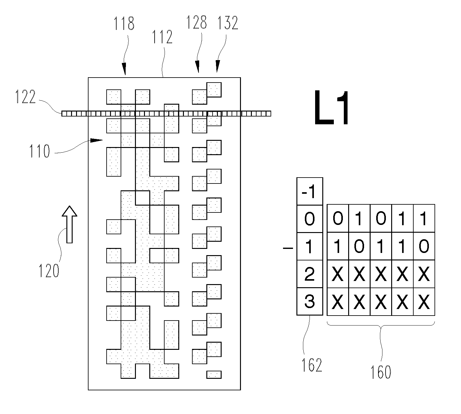
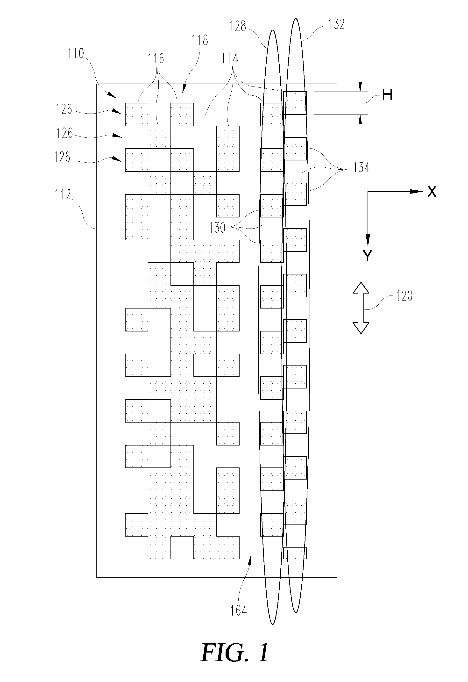
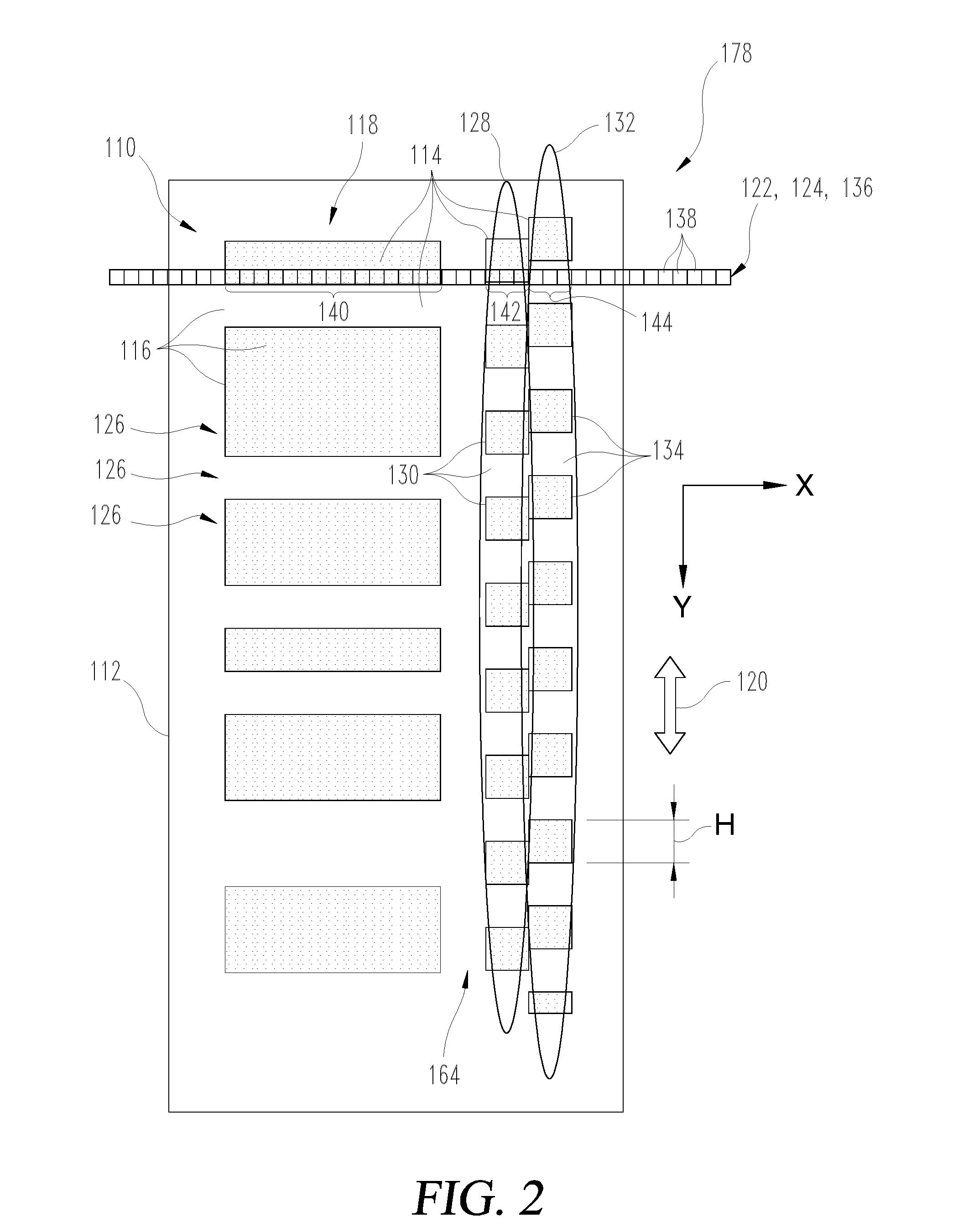
[0107]As illustrated above, one idea of the present invention comprises reading out a barcode in such a way that two mutually phase-offset and sometimes coincident signals from a clock track detector and from a reference detector are compared. Here, these can either be signals which were recorded by means of the same clock track but with a spatial phase offset with respect to one another, or signals from a clock track and a separate, phase-shifted reference track of the barcode. Combinations of these options, or other embodiments by means of which the phase-offset signals can be produced, are also feasible.

[0108]FIGS. 1 and 2 illustrate, in an exemplary fashion, exemplary embodiments of two different embodiments of optical barcodes 110. By way of example, the barcodes 110 can each be applied to a carrier 112 or be con...


PUM

PropertyMeasurementUnit
angle tolerancesaaaaaaaaaa

Abstract

Barcodes are provided that are applied to or integrated with a moving carrier, where the barcodes have a plurality of information modules, at least one clock track having a plurality of alternating clock track modules and at least one reference track having a plurality of alternating reference track modules, where the at least one reference track is a second clock track and has a same periodicity as the clock track but a spatial phase shift when compared to the clock track. The barcode is configured to allow at least one barcode reader to determine a direction of movement of the carrier from at least one signal from a clock track detector and at least one signal from a reference detector.

Description

CROSS-REFERENCE TO RELATED APPLICATIONS[0001]This patent application is a continuation of U.S. patent application Ser. No. 13 / 854,294 (filed 1 Apr. 2013), now U.S. Pat. No. 9,235,744 (issued 12 Jan. 2016), which is a continuation of Int'l Patent Application No. PCT / EP2011 / 066993 (filed 29 Sep. 2011), which claims priority to and the benefit of EP Patent Application No. 10186031.0 (filed 1 Oct. 2010). Each patent application is incorporated herein by reference as if set forth in its entirety.TECHNICAL FIELD[0002]The invention relates to a barcode reader for capturing an optical barcode connected to a moved carrier. The invention furthermore relates to a device for transmitting at least one item of information, comprising a barcode reader according to the invention and a carrier with an optical barcode. The invention furthermore relates to a barcode, in particular for marking a consumable article, more particularly an analytic test element for use in a device according to the inventio...

Claims


Application Information

Patent Timeline
Patent Type & Authority Patents(United States)
IPC IPC(8): G06K7/10G06K7/14G06F17/30G06K7/01G06K19/06G01N35/00
CPCG06K19/06046G06F17/30G06K7/10722G06K7/10762G06K7/1413G06K7/1417G06K7/1456G06K19/06028G06K19/06037G01N2035/00752G06K2007/10504G06F16/00G06K7/10
Inventor HENSEL, UWESCHMELZEISEN-REDEKER, GUENTHER
Owner ROCHE DIABETES CARE INC
Why Eureka
Try Eureka