Articulated Thermal Processing Torch

a technology of thermal processing torch and articulating shaft, which is applied in the direction of welding coupling means, manufacturing tools, welding apparatus, etc., can solve the problems of not being able to reach the market, difficulty in accessing workpiece parts, and the use of hand-held torches in ever more intricate ways

Active Publication Date: 2009-02-12
HYPERTHERM INC
View PDF19 Cites 30 Cited by
  • Summary
  • Abstract
  • Description
  • Claims
  • Application Information

AI Technical Summary

Benefits of technology

[0034]FIG. 3 shows a cut-away view of a pivotal connector for a thermal p

Problems solved by technology

Hand-held torches are now being used in ever more intricate situations, including those where access to portions of the workpiece can be difficult.
Technical hurdles related to the articulated joint have thus far prevented such concepts from reaching the market.
One issue preventing certain manufacturers from entering the articulated torch market has been the extensive use of torch designs with moving plungers inside the torch head.
These “blowback” designs

Method used


Image

  • Articulated Thermal Processing Torch
  • Articulated Thermal Processing Torch
  • Articulated Thermal Processing Torch

Examples


Embodiment Construction

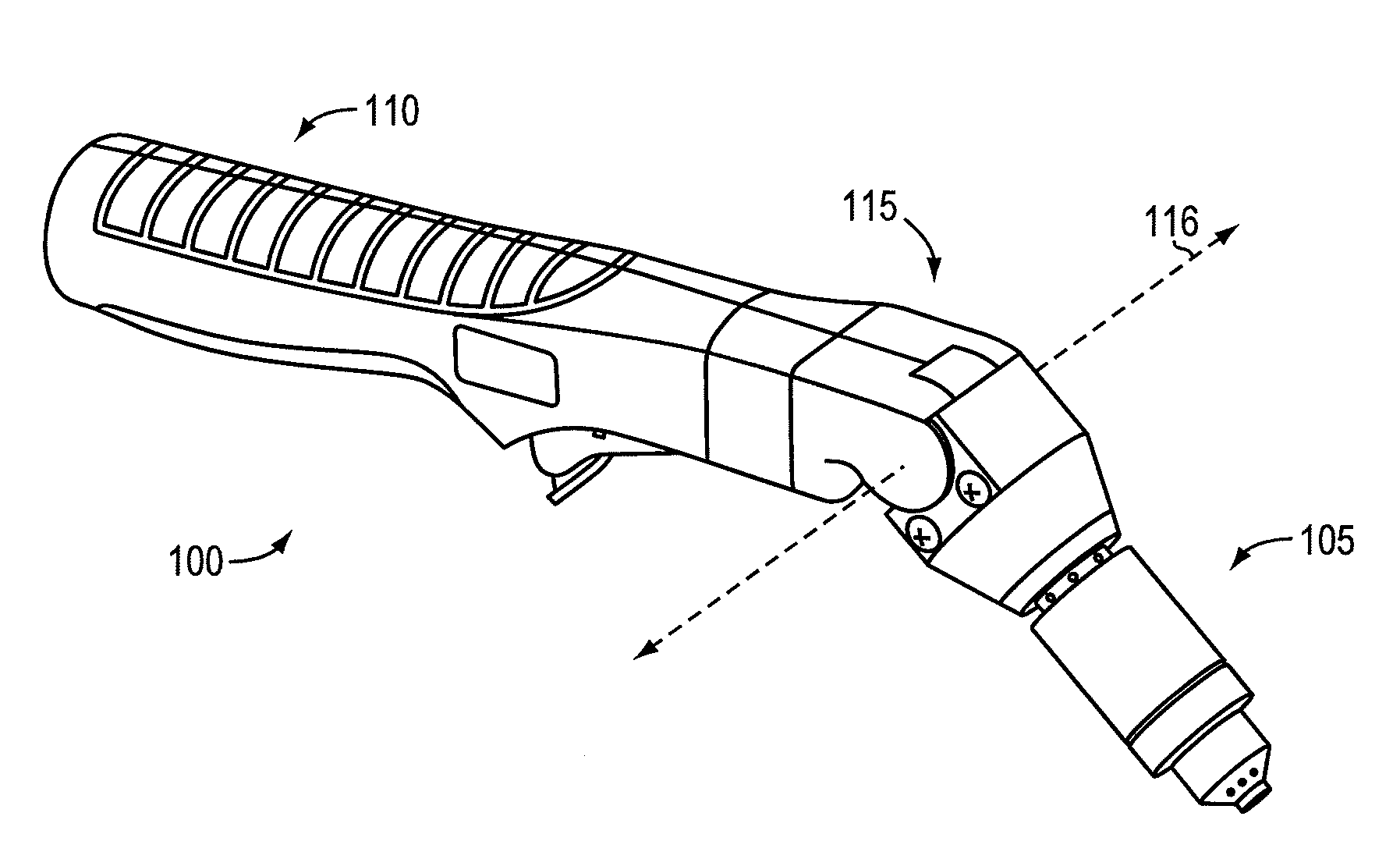
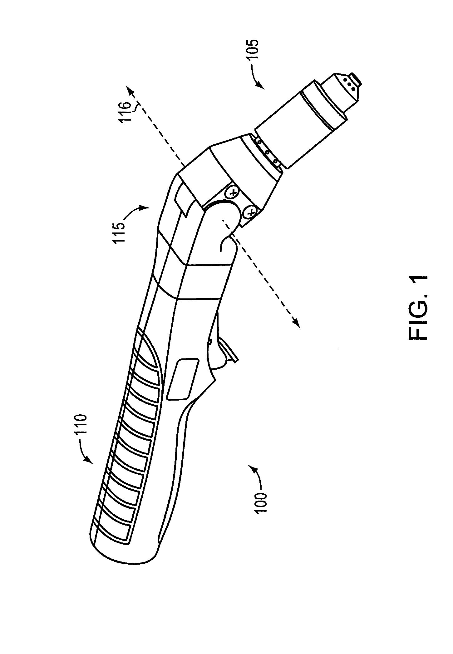
[0045]FIG. 1 shows a perspective view of an articulating thermal processing torch 100 (e.g., welding or plasma arc torch), according to an illustrative embodiment. The thermal processing torch 100 can include a torch housing (e.g., external torch housing) having a head portion 105 pivotally coupled or pivotally attached relative to a body portion 110 with a joint portion 115. The torch 100 can also include a pivotal connector (not shown) that simultaneously pivots about a common axis 116 with the joint portion 115 of the external torch housing.

[0046]In some embodiments, a torch100 includes a pilot wire passing a pilot current between the body portion 110 and the head portion 105. The torch 100 can also include cap sensor switch wires extending between the body portion 110 and the head portion 105. At least one pilot wire, cap sensor wire, or any combination thereof, can extend through the joint portion 115 of the torch 100.

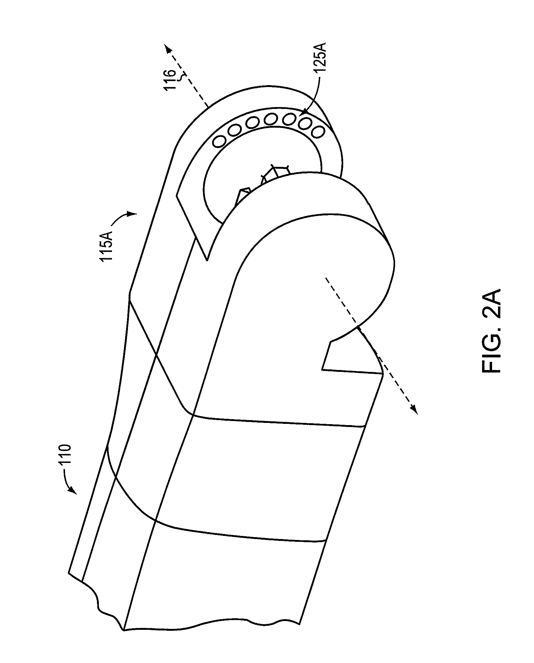
[0047]FIG. 2A shows a mating portion 115A of the joint porti...


PUM

PropertyMeasurementUnit
Angleaaaaaaaaaa
Angleaaaaaaaaaa
Electrical conductivityaaaaaaaaaa

Abstract

A thermal processing torch can include a torch housing having a head portion pivotally coupled relative to a body portion with a joint portion. The torch also can include a pivotal connector simultaneously pivoting about a common axis with the joint portion of the torch housing. The pivotal connector can include an electrically conductive wall conducting an electrical current between the body portion of the torch housing and the head portion of the torch housing. The pivotal connector can also include a passage provide a processing gas between the body portion of the torch housing and the head portion of the torch housing.

Description

CROSS-REFERENCE TO RELATED APPLICATION[0001]This application claims the benefit of and priority to U.S. provisional patent Application No. 60 / 963,586 filed on Aug. 6, 2007, the disclosure of which is incorporated herein by reference in its entirety.FIELD OF THE INVENTION[0002]The invention relates generally to the high temperature thermal processing of materials, such as with plasma arc torches, and the cutting of materials. More specifically, the invention relates to an articulated thermal processing torch in which electrical and fluid flows are routed through a pivotal connection.BACKGROUND OF THE INVENTION[0003]Plasma arc torches are used in the cutting and marking of metallic materials. A plasma arc torch generally includes a torch body, an electrode mounted within the body, a nozzle with a central exit orifice, electrical connections, passages for cooling and arc control fluids, a swirl ring to control the fluid flow patterns, and a power supply. Gases used in the torch can be ...

Claims


Application Information

Patent Timeline
IPC IPC(8): B23K9/00
CPCH05H1/34B23K9/323H05H1/3423
Inventor TWAROG, PETER J.HANSEN, BRETT ANDREW
Owner HYPERTHERM INC
Why Eureka
Try Eureka