Drawer Actuator and Latch System

a technology of latch system and actuator, which is applied in the direction of building locks, lock casings, constructions, etc., can solve the problems of difficult mounting of actuators

Inactive Publication Date: 2009-02-12
ILLINOIS TOOL WORKS INC
View PDF6 Cites 19 Cited by
  • Summary
  • Abstract
  • Description
  • Claims
  • Application Information

AI Technical Summary

Problems solved by technology

In a number of drawer environments the mounting of actuators has proven to be difficult due to the need to secure the actuators in a fixed

Method used


Image

  • Drawer Actuator and Latch System
  • Drawer Actuator and Latch System
  • Drawer Actuator and Latch System

Examples


Embodiment Construction

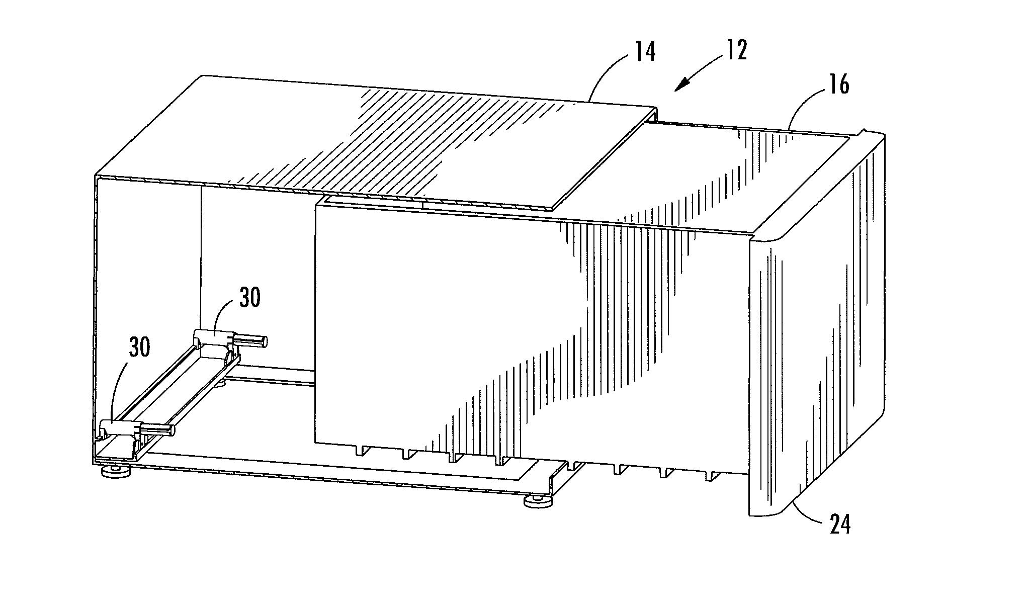
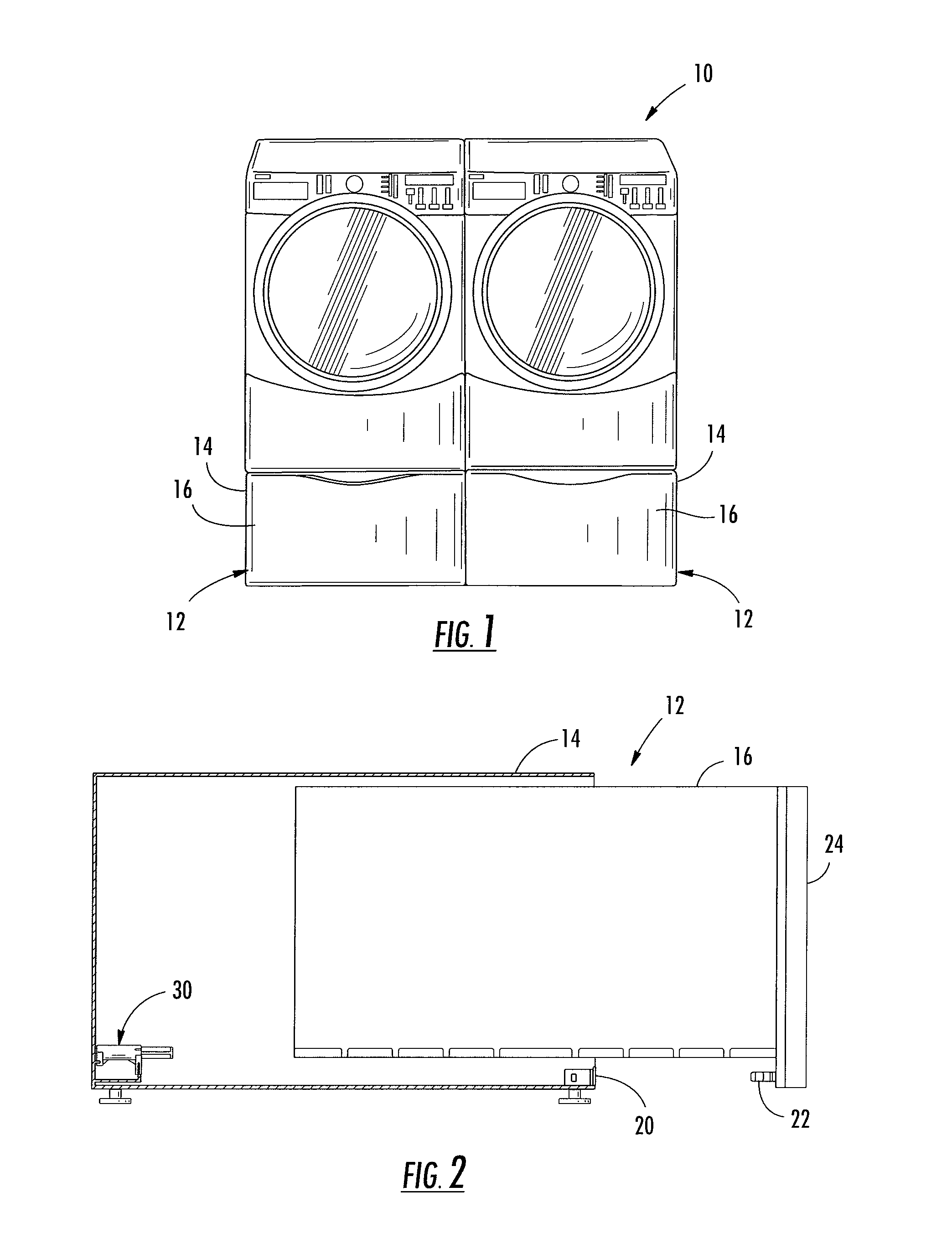
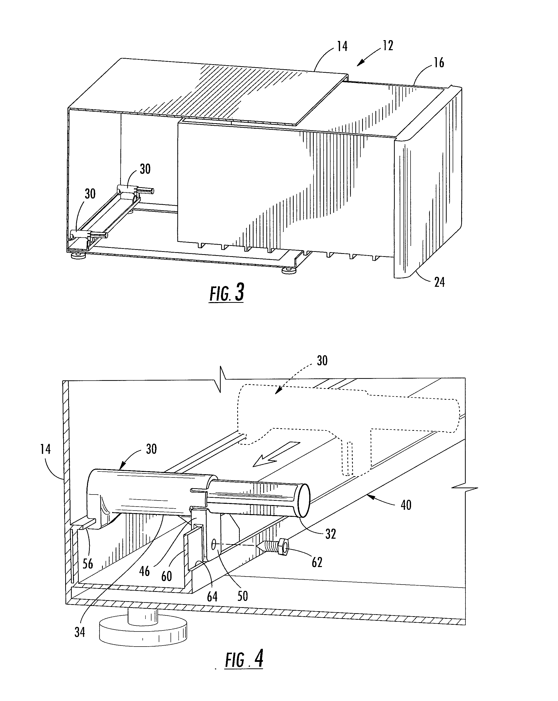
[0018]Turning now to the drawings, in FIG. 1 there is illustrated an appliance system 10 such as a clothes washer and dryer or the like. In the illustrated arrangement, each of the appliances in the appliance system 10 includes a user manipulated drawer system 12 including a cabinet structure 14 and a user manipulated sliding drawer 16. Of course, it is to be understood that the drawer system 12 is in no way limited to use within an appliance system. Rather, a drawer system 12 consistent with the present disclosure may be utilized in any suitable environment where storage is required.

[0019]As best illustrated through joint reference to FIGS. 2 and 3, the illustrated exemplary drawer system 12 incorporates a latch assembly 20 mounted adjacent an edge of a drawer acceptance opening within the cabinet structure 14. The latch structure 20 is preferably a so called “push-push” latch assembly of a type well known to those of skill in the art adapted to matedly engage a strike element 22 e...


PUM


Abstract

A drawer manipulation system adapted to facilitate opening of a drawer supported within a cabinet. The system includes at least one biasing actuator adapted for mounting in supported relation at projecting edge elements within the cabinet housing the drawer. The actuator incorporates an arrangement of slotted engagement surfaces adapted to accept supporting edge structures. The actuator may be used in conjunction with a push-push latch assembly.

Description

CROSS REFERENCE TO RELATED APPLICATION[0001]This Non-Provisional Application claims benefit to U.S. Provisional Application Ser. No. 60 / 964,299 filed Aug. 10, 2007, the contents of which are incorporated herein by reference in their entirety.FIELD OF THE INVENTION[0002]The present invention relates generally to a drawer manipulation system to facilitate opening and, more particularly, to a system incorporating a biasing drawer actuator mountable in supported relation relative to projecting edge portions of a cabinet frame structure.BACKGROUND OF THE INVENTION[0003]Drawer manipulation systems using biasing actuators and cooperating latch structures are generally known. Such drawer actuators operatively engage a rear portion of the drawer when the drawer is in a closed position so as to urge the drawer towards an open position to permit access to the interior by a user. When the drawer is in the closed position, a latch assembly is engaged to resist the biasing opening force provided ...

Claims


Application Information

Patent Timeline
IPC IPC(8): A47B88/04
CPCA47B88/0477E05B9/08E05Y2201/264E05C19/02E05Y2201/212E05B65/44A47B88/463E05B65/46
Inventor WONG, CHONG B.
Owner ILLINOIS TOOL WORKS INC
Why Eureka
Try Eureka