Fly-cutting system and method, and related tooling and articles

Inactive Publication Date: 2009-02-12
3M INNOVATIVE PROPERTIES CO
View PDF47 Cites 61 Cited by
  • Summary
  • Abstract
  • Description
  • Claims
  • Application Information

AI Technical Summary

Benefits of technology

[0022]FIG. 12 is a cross-sectional view of a portion of an idealized fly-cutting head with a less sharp or dull cutting element cutting a groove or groove segment into a workpiece;
[0023]FIG. 13 is a sectional cut-away view of a portion of a tool cut in accordance with the prior art, exhibiting a virtual seam; and
[0024]FIG. 14 is a sectional cut-away view of a portion of a tool cut in accordance with the present invention.

Problems solved by technology

This method can result in the formation of the initial portions of the features or grooves near the first end of the workpiece that are relatively sharper than the subsequent portions of the features or grooves formed closer to the second end of the workpiece.

Method used


Image

  • Fly-cutting system and method, and related tooling and articles
  • Fly-cutting system and method, and related tooling and articles
  • Fly-cutting system and method, and related tooling and articles

Examples


Embodiment Construction

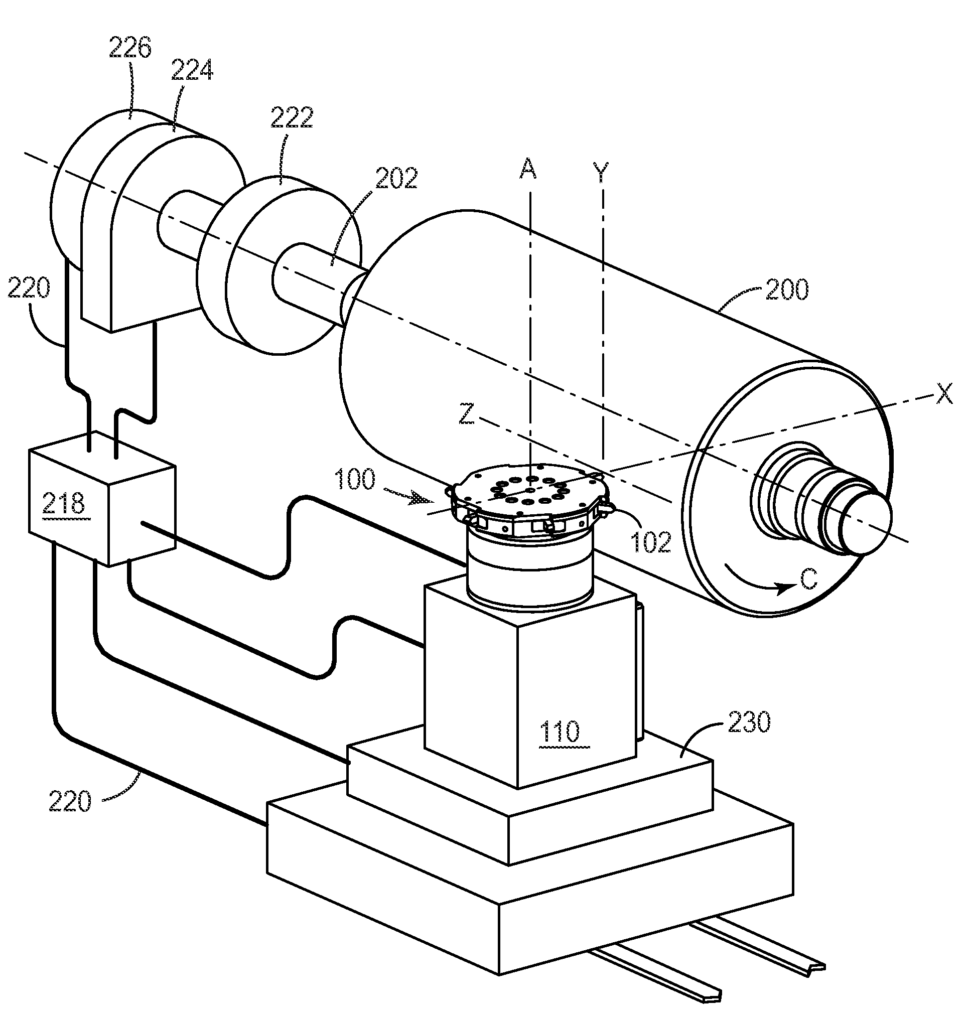
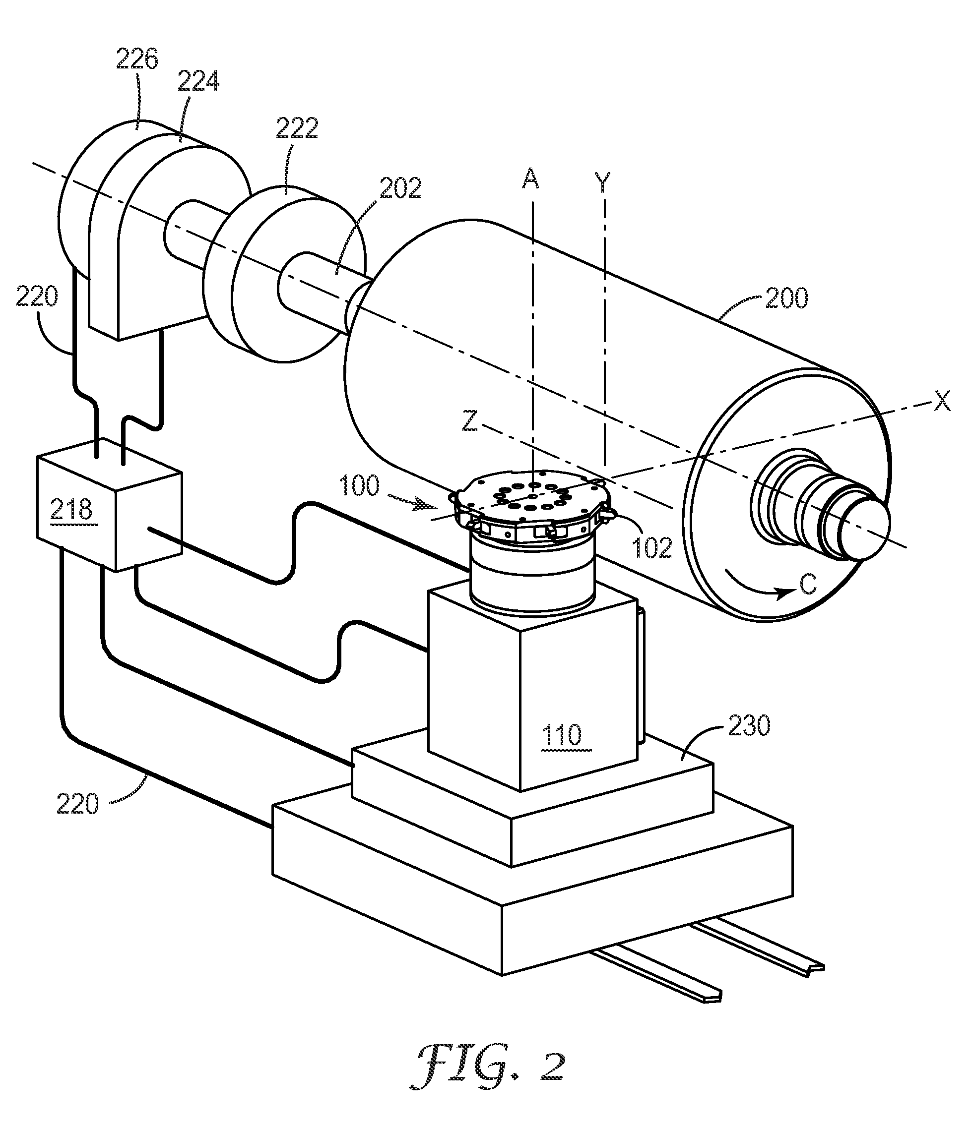
[0025]In conventional fly-cutting operations, a fly-cutter is positioned relative to a workpiece, a motor is activated to rotate the head and the associated cutting element or elements, and the fly-cutting head is moved relative to the workpiece to cut a groove or other feature into the workpiece. Fly-cutting, which is a type of milling, is typically a discontinuous cutting operation, meaning that each cutting element is in contact with the workpiece for a period of time, and then is not in contact with the workpiece for a period of time during which the fly-cutting head is rotating that cutting element through the remaining portion of a circle until it again contacts the workpiece. Although a fly-cutting operation is typically discontinuous, the resulting groove segment or other surface feature formed in a workpiece by the fly-cutter may be continuous (formed by a succession of individual, but connected cuts, for example) or discontinuous (formed by disconnected cuts), as desired. ...


PUM

PropertyMeasurementUnit
diameteraaaaaaaaaa
depthaaaaaaaaaa
depthaaaaaaaaaa

Abstract

Methods of fly-cutting a workpiece are disclosed, and in methods in which the position of a fly-cutting head or its associated cutting element is known as a function of time. Also disclosed are methods of forming features, such as grooves or groove segments, in a workpiece such as a cylindrical roll. The features may be provided according to one or more disclosed patterns. Articles made using tools machined in the manner described are also provided, such as polymeric film or sheeting that exhibit certain beneficial properties.

Description

RELATED APPLICATIONS [0001]This application is generally related to the subject matter of U.S. Patent Application Ser. No. ______, entitled “Fly-cutting Head, System and Method, and Tooling and Sheeting Produced Therewith,” Attorney file number 62782US002, which was commonly assigned to the assignee of the present invention, was filed on the same date as the present application, and is incorporated by reference herein.TECHNICAL FIELD [0002]The invention relates to machining systems and methods, and in particular to fly-cutting systems and methods and related tooling and articles.BACKGROUND OF THE INVENTION [0003]One method of machining grooves or other features into a workpiece is to use a rotating fly-cutting head to bring a cutting element into contact with the workpiece. The head and the workpiece can be moved relative to each other, which enables the cutting element to cut a long groove into the workpiece, for example. If the workpiece is a cylindrical roll, a fly-cutting head c...

Claims


Application Information

Patent Timeline
Patent Type & Authority Applications(United States)
IPC IPC(8): B23B35/00B23D77/00
CPCB23C3/30Y10T82/2529B23C2226/125B23C2226/31B23Q15/007G05B19/182G05B2219/50213Y10T428/24355Y10T82/10Y10T409/303752Y10T408/03Y10T428/24479Y10T82/2587Y10T408/909B23C5/08B29C37/0057B29C2793/0009G02B5/045G02B5/1852Y10T409/108745
Inventor BURKE, JAMES P.CAMPBELL, ALAN B.EHNES, DALE L.WERTZ, DANIEL S.
Owner 3M INNOVATIVE PROPERTIES CO
Why Eureka
Try Eureka