System and method for three-dimensional ultrasound imaging

a three-dimensional ultrasound and imaging system technology, applied in the field of ultrasound imaging, can solve the problems of pain for patients, the need to heal the area from which the tissue sample was removed, and the patient's health adverse effects,

Active Publication Date: 2009-02-12
SJ STRATEGIC INVESTMENTS LLC
View PDF5 Cites 156 Cited by
  • Summary
  • Abstract
  • Description
  • Claims
  • Application Information

AI Technical Summary

Benefits of technology

[0025]In some embodiments, at least a subset of the rows have a different lateral dimension than other of the rows. In some embodiments, the lens is made of a material having a speed of sound of less than 1.5 mm/μs. In some embodiments, the material comprises one of silicone and urethane.
[0026]Under another aspect, a method of multiplexing signals from tran

Problems solved by technology

Invasive procedures like the biopsy have inherent drawbacks, such as pain for the patient, and the need to heal the area from which the tissue sample was removed.
However, while non-invasive techniques are painless and do not require healing time, they may still pose certain dangers to the patient.
For example, an unhealthy dose of X-ray radiation may lead to cancer.
The strong magnetic fields produced by an MRI machine may also cause adverse health effects in the patient.
However, a narrower elevation aperture provides less effective focusing, and hence results in a lower lateral resolution.
However, these kinds of arrays suffer from limited pene

Method used


Image

  • System and method for three-dimensional ultrasound imaging
  • System and method for three-dimensional ultrasound imaging
  • System and method for three-dimensional ultrasound imaging

Examples


Embodiment Construction

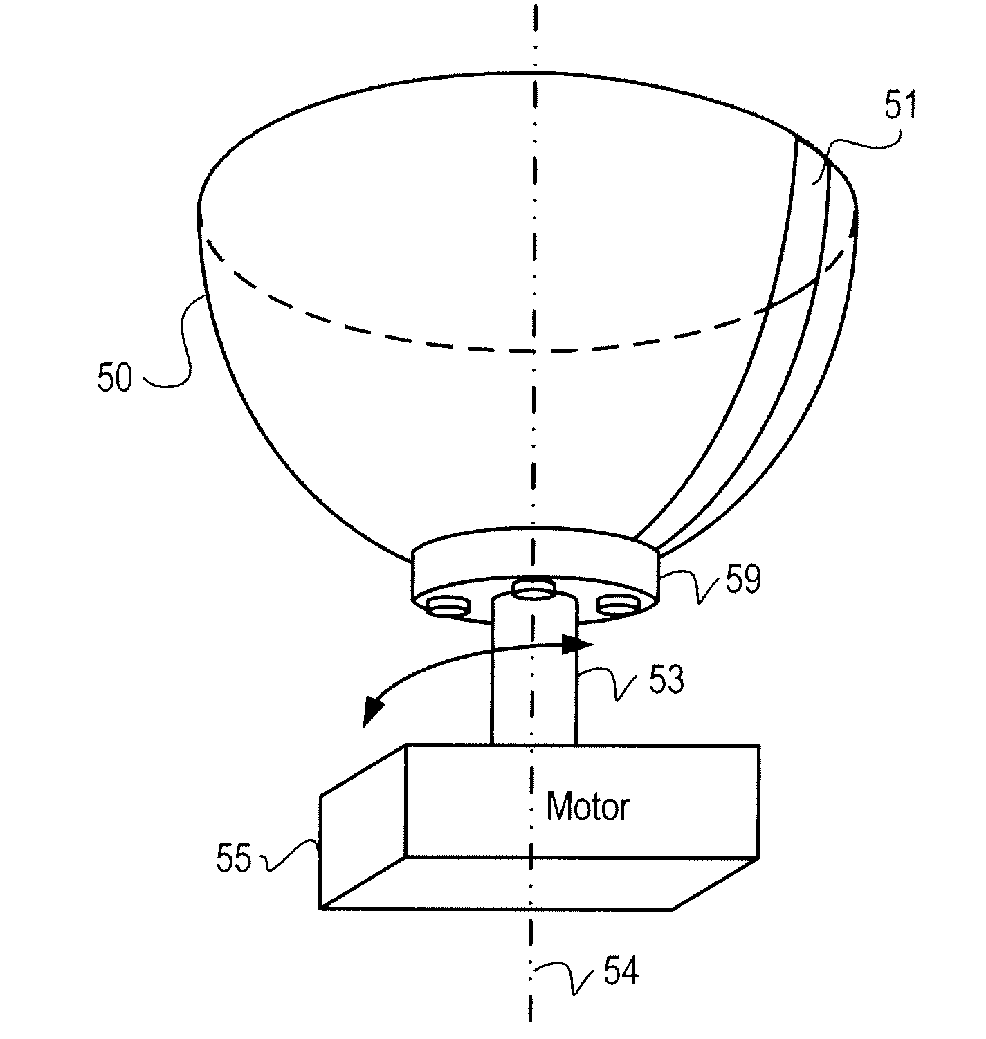
[0054]FIGS. 4-12 illustrate some embodiments of a 3D ultrasound imaging system 40. FIG. 4 illustrates a high-level overview of the components of system 40. System 40 includes a dome 50, a concave transducer array 52, a multiplexing structure 90 attached to the transducer array 52, a beamformer 41, an amplifier and gain control 42, a processor 45 with memory 46, and a display 49. The beamformer 41, multiplexer 90, amplifier and gain control 42, and processor 45 are all coupled to one another.

[0055]To create a 3D image of a particular part of human anatomy, the operator positions the part of human anatomy to be imaged inside the imaging dome 50. The system 40 can be used to image almost any part of the human body, depending on the size of the dome. For example, a shoulder, breast, wrist, ankle, elbow, or other parts of human anatomy can be positioned inside the dome. As will be understood by those of ordinary skill in the art, this can be accomplished by a variety of methods. One appr...


PUM


Abstract

Under one aspect, an ultrasound system for producing a representation of an object includes: a concave transducer array configured to transmit ultrasonic pulses into the object and to receive ultrasonic pulses from the object, the ultrasonic pulses from the object containing structural information about the object, each transducer in the array generating an output signal representative of a portion of the structural information about the object; a multi-focal lens structure for focusing the transmitted ultrasonic pulses; a multiplexing structure in operable communication with the concave transducer array and including logic for coupling the output signals from at least one pair of transducers in the concave transducer array; and a beamformer in operable communication with the multiplexing structure and including logic for constructing a representation of structural information about the object based on the coupled output signals from the multiplexing structure.

Description

RELATED APPLICATIONS[0001]This application claims the benefit of U.S. Provisional Patent Application No. 60 / 954,222, filed Aug. 6, 2007 and entitled “System and Method for Three-Dimensional Ultrasound Imaging,” the entire contents of which are incorporated by reference herein.[0002]This application also claims the benefit of U.S. Provisional Patent Application No. 60 / 986,770, filed Nov. 9, 2007 and entitled “Freestanding Ultrasonic Breast Scanning System,” the entire contents of which are incorporated by reference herein.FIELD OF THE INVENTION[0003]This application generally relates to ultrasonic imaging, and more particularly to medical three-dimensional ultrasound imaging systems.BACKGROUND OF THE INVENTION[0004]Timely diagnosis of potential ailments is perhaps the most effective tool available to modern physicians in their battle against serious illnesses. If discovered early enough, many of the deadliest illnesses and diseases pose little threat to a patient with proper treatmen...

Claims


Application Information

Patent Timeline
IPC IPC(8): A61B8/14
CPCA61B8/0825A61B8/13A61B8/406A61B8/4483A61B8/483B06B1/0629A61B8/4494G01S7/52085G01S15/892G01S15/8925G01S15/894G01S15/8993G01S7/52046A61B5/7264A61B8/145A61B8/4461A61B8/5207A61B8/5253A61B2560/0475G10K11/30
Inventor TOWFIQ, FARHADBUSSE, LAWRENCE J.DOUGLAS, STEPHEN J.
Owner SJ STRATEGIC INVESTMENTS LLC
Why Eureka
Try Eureka