Storage system and method of designing disaster recovery constitution

a technology of disaster recovery and storage system, applied in the field of storage system and a method of designing can solve the problems of time and effort, data processing services cannot be provided for the host, and the investigation and design of a disaster recovery constitution take time and effor

Active Publication Date: 2009-02-19
RAKUTEN GRP INC
View PDF9 Cites 22 Cited by
  • Summary
  • Abstract
  • Description
  • Claims
  • Application Information

AI Technical Summary

Problems solved by technology

However, in cases where a fault occurs at the only backup site prior to recovery of the main site, data processing services cannot be provided for the host.
In a storage system comprising a multiplicity of sites, because the overall constitution of the system is complicated, it takes effort to construct a suitable disaster recovery constitution that satisfies user expectations.
Therefore, by considering a plurality of parameters for the multiplicity of sites, the user must design the disaster recovery constitution that is considered most appropriate, and this investigation and design of the disaster recovery constitution take time and effort.

Method used


Image

  • Storage system and method of designing disaster recovery constitution
  • Storage system and method of designing disaster recovery constitution
  • Storage system and method of designing disaster recovery constitution

Examples


first embodiment

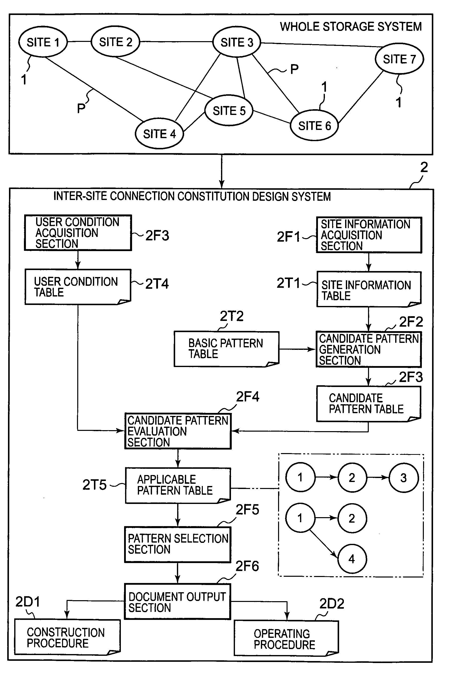
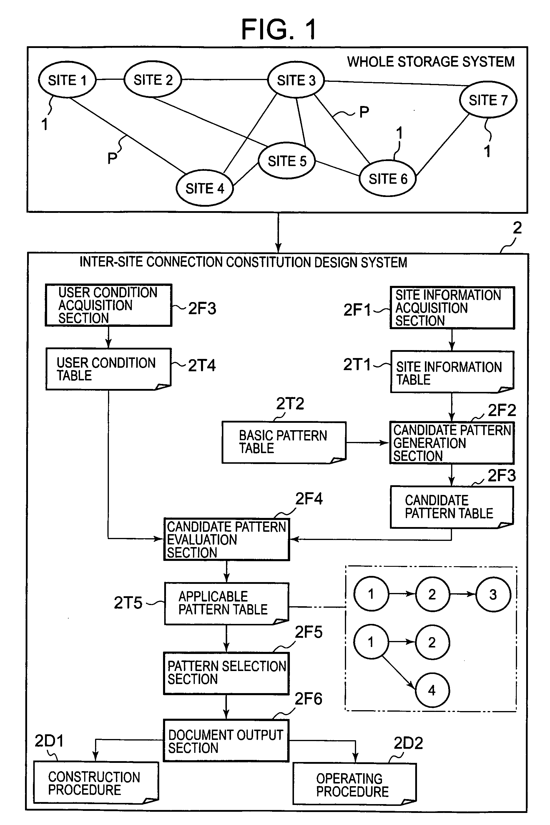
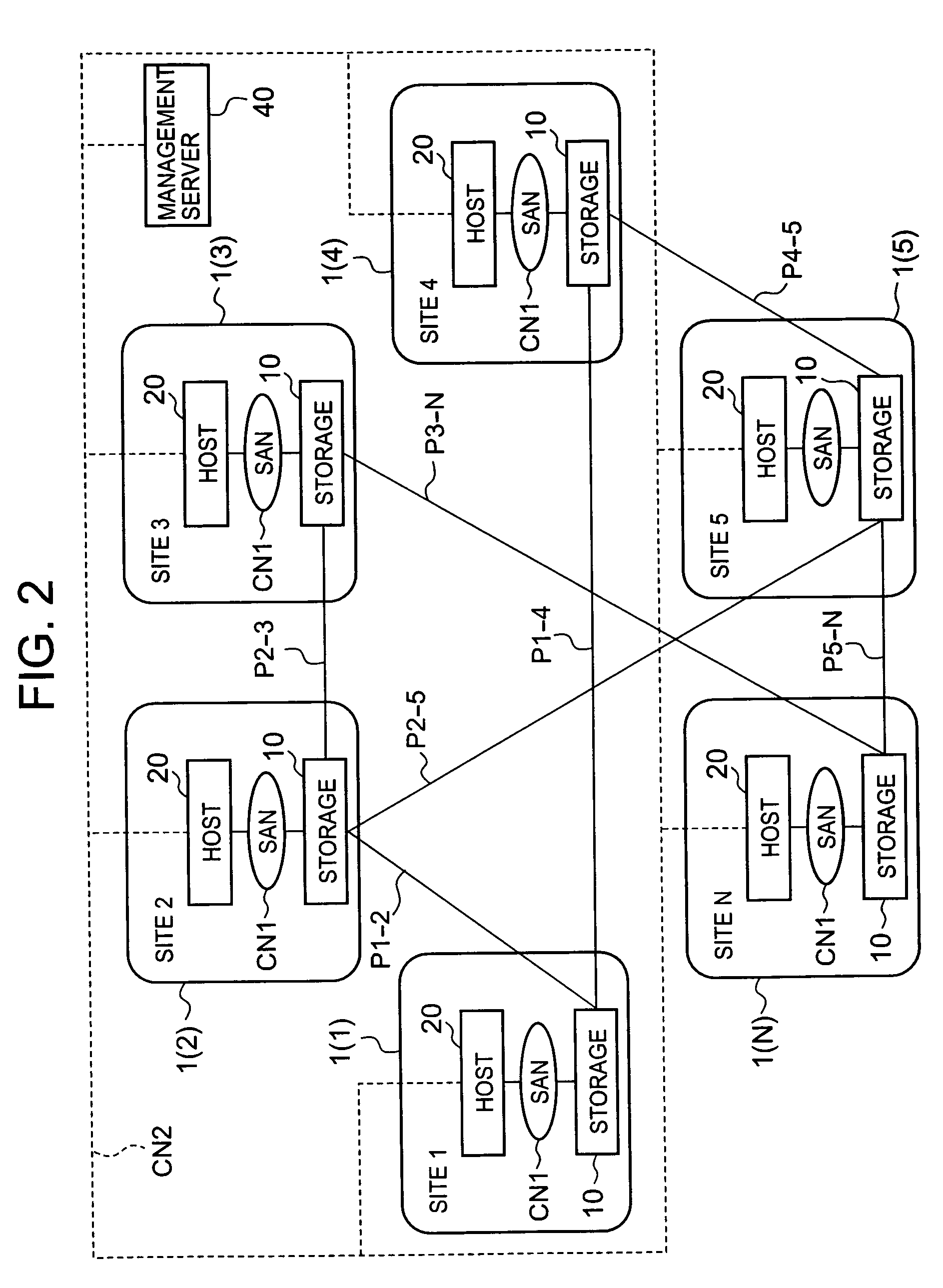
[0065]FIG. 2 is an explanatory diagram showing the overall constitution of the storage system according to the present invention. The storage system comprises a plurality of sites 1 (1) to 1(N) (four or more, for example). In the following description, in cases where there is no particular need to distinguish the respective sites, the sites are referred to simply as ‘sites 1’. The respective sites 1 can be disposed in different cities, for example. The respective sites 1 comprise a storage device 10 which constitutes a ‘storage control device’ and a host 20 which is a ‘higher-level device’. The storage device 10 and host 20 are connected via an intra-site network CN1 such as a SAN (Storage Area Network), for example.

[0066]As indicated by FIG. 1, predetermined sites among the respective sites 1 are connected via a remote copy communication path P. The respective sites 1 are connected via a management network CN2 such as the Internet, for example. The respective sites 1 confirm the vi...

second embodiment

[0124]The second embodiment of the present invention will now be described based on FIG. 17. This embodiment corresponds to a modified example of the first embodiment. In this embodiment, the management server 40 continually monitors changes to the constitution of the storage system in order to keep the site information table T1 in the latest state.

[0125]FIG. 17 is a flowchart showing the processing to update the site information table T1 which is executed by the management server 40. The management server 40 first generates and stores a site information table T1 based on the initial state of the storage system (S100). The initial site information table T1 is generated based on the site information that is input from the user terminal, for example.

[0126]The management server 40 monitors whether changes to the constitution in the storage system have occurred (S101). Constitutional changes can include, for example, the addition of new sites, the withdrawal of existing sites, changes t...


PUM


Abstract

The present invention detects patterns that conform to the user conditions in cases where a disaster recovery constitution is constructed by connecting a plurality of sites. The design system is used in cases where the disaster recovery constitution is provided in a storage system. The site information acquisition section acquires information relating to the constitution in the sites and information relating to the connections between the sites, and stores the information in the site information table. The candidate pattern generation section generates candidate patterns for each of the parameters on the basis of the site information table and a basic pattern table. The candidate pattern evaluation section evaluates the respective candidate patterns by using the user condition table and presents patterns which conform to the user conditions to the user. The document output section generates a construction procedure and operating procedure on the basis of patterns selected by the user.

Description

CROSS-REFERENCE TO RELATED APPLICATIONS[0001]This application relates to and claims priority from Japanese Patent Application No. 2007-180728 filed on Jul. 10, 2007, the entire disclosure of which is incorporated herein by reference.BACKGROUND OF THE INVENTION[0002]1. Field of the Invention[0003]The present invention relates to a storage system and a method of designing a disaster recovery constitution.[0004]2. Description of the Related Art[0005]The storage system comprises at least one storage control device called a ‘disk array system’ or the like, for example and provides a host computer (‘host’ hereinbelow) with data storage services. The storage control device can have a multiplicity of disk drives arranged in an array to construct a RAID (Redundant Array of Independent Disks)—based storage area.[0006]Further, as is known for a so-called disaster recovery system, a backup site can also be provided in a location that is remotely separated from the main site in preparation for a...

Claims


Application Information

Patent Timeline
Patent Type & Authority Applications(United States)
IPC IPC(8): G06F11/00
CPCG06F17/30067G06F16/10
Inventor HATTORI, KUNIHIROSHOJI, TOMOKI
Owner RAKUTEN GRP INC
Why Eureka
Try Eureka