Bed load detector

a load detector and bed leg technology, applied in the field of bed leg load detectors, can solve the problems of difficult work for putting the bed leg on and off the load detector, and difficulty in getting on and out of the bed,

Inactive Publication Date: 2009-02-26
SHOWA DENKO KK
View PDF11 Cites 19 Cited by
  • Summary
  • Abstract
  • Description
  • Claims
  • Application Information

AI Technical Summary

Benefits of technology

[0096]With the invention as recited in the aforementioned item 25, the operation result of the operation means can be displayed certainly.
[0097]With the invention as recited in the aforementioned item 26, in cases where the operation result of the operation means falls outside the set range, an alarm can be given to a nurse, a care worker, a guard, etc.
[0098]With the invention as recited in the aforementioned item 27, it is detectable whether the subject is occupying the bed at a remote place.
[0099]With the invention as recited in the aforementioned item 28, the above effect of the invention as recited in any one of the aforementioned items 1 to 23 can be obtained. Furthermore, it is possible to certainly detect whether the subject is occupying the bed.
[0100]With the invention as recited in the aforementioned item 29, the above effects of the invention as recited in any one of the aforementioned items 1 to 23 can be obtained. Furthermore, it is possible to certainly monitor whether the subject is occupying the bed.

Problems solved by technology

This causes difficulty of getting on and out of the bed by a subject and makes the work for putting the bed leg on and off the load detector difficult.

Method used


Image

  • Bed load detector
  • Bed load detector
  • Bed load detector

Examples


first embodiment

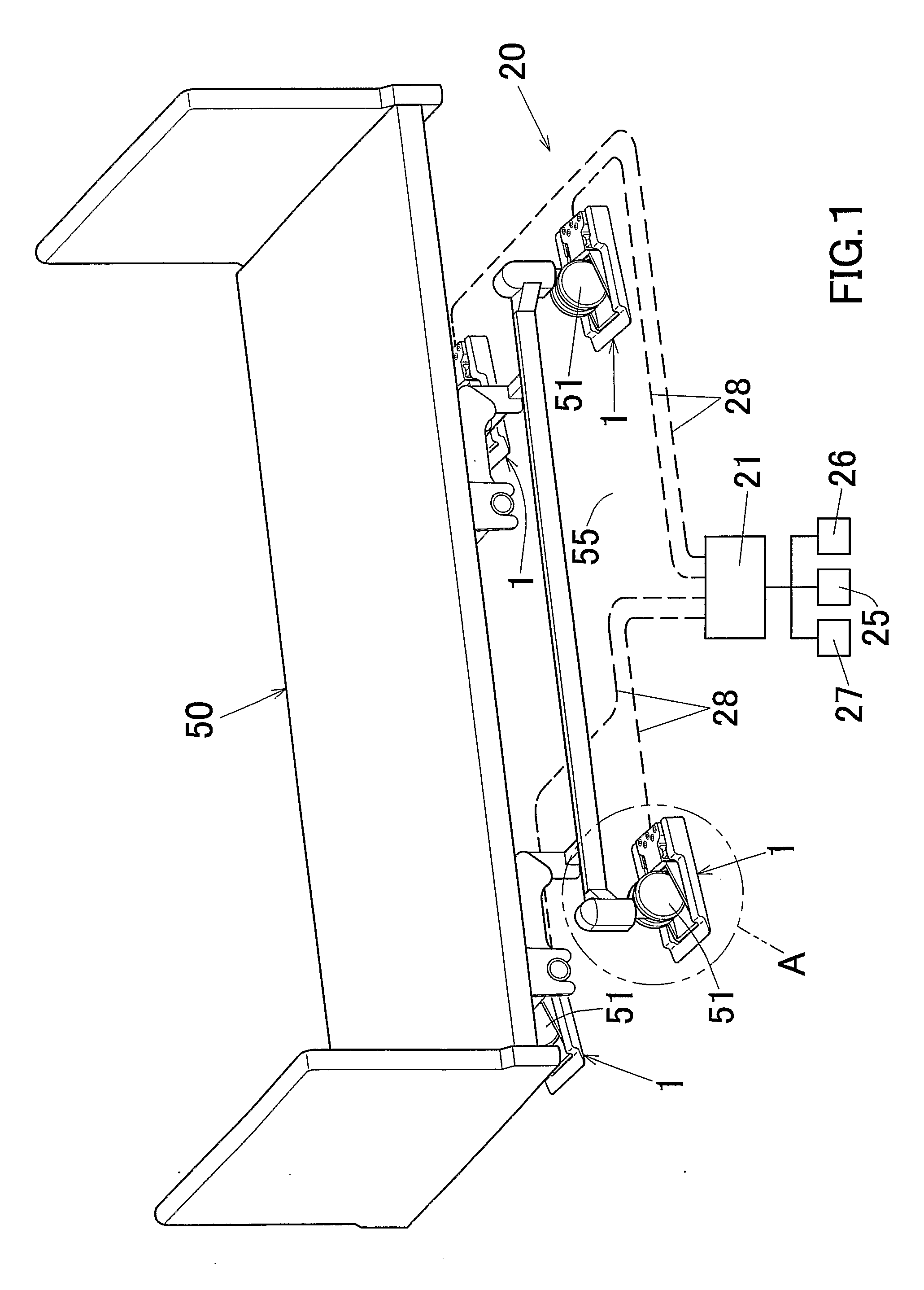
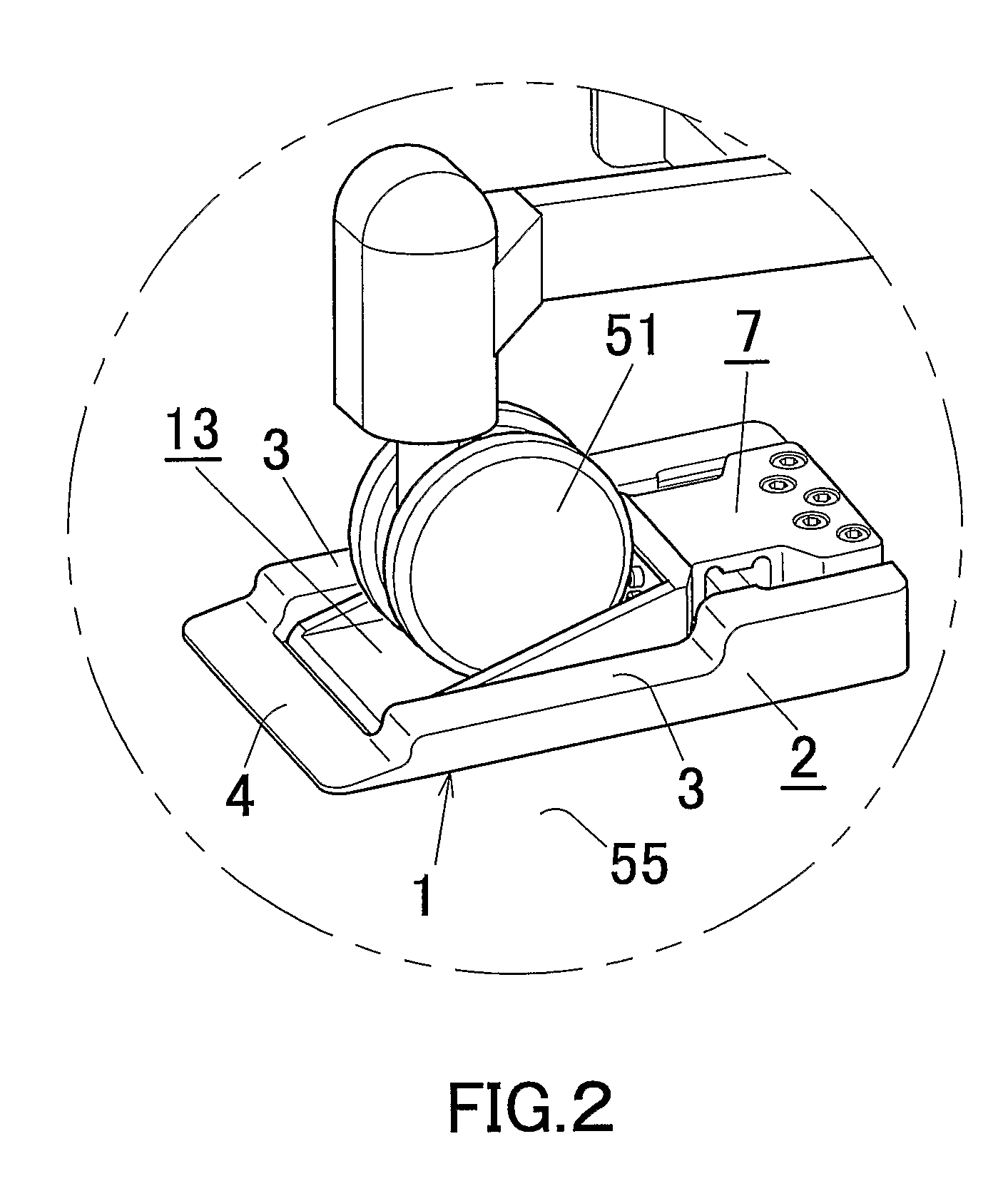
[0129]In FIG. 1, the reference numeral “1” denotes a bed load detector according to the invention, and the reference numeral “20” denotes a bed occupancy detecting apparatus according to an embodiment of the invention. And, the reference numeral “50” denotes a bed.

[0130]The bed 50 is used at medical facilities (e.g., hospitals), aged person institutions, nursing-care facilities, ordinary homes, etc., and is formed into a rectangular shape as seen from the top. This bed 50 has a plurality of leg portions. Specifically, it has a total of four leg portions, i.e., a leg portion located at the left side of a head of a subject (not shown), a leg portion located at the light side of the head of the subject, a leg portion located at the side of the left leg of the subject, and a leg portion located at the side of the right leg of the subject. In this embodiment, each leg portion of the bed 50 is provided with a rotatable bed moving caster 51 for running on a bed installation surface 55 at t...

third embodiment

[0205]Furthermore, at both side edge portions of the leg disposing plate portion 13, as caster fall preventing means (i.e., leg portion fall preventing means), a pair of caster fall prevention wall portions 14B and 14B (i.e., leg portion fall preventing wall portions) upwardly protruded with respect to the upper surface 13a of the leg disposing plate portion 13 is integrally formed. In this third embodiment, as shown in FIG. 17, both the caster fall prevention wall portions 14B and 14B are integrally formed in such a manner that the distance therebetween gradually increases in a direction opposite to the traveling direction C of the caster 51, in other words, the distance therebetween gradually decreases in the traveling direction C of the caster 51. The distance between the rear end portions of both the caster fall prevention wall portions 14B and 14B is set so as to fall within the range of 70 to 100 mm, and the distance between the front end portions of both the caster fall preve...


PUM


Abstract

A load detector 1 is provided with a base plate portion 2 to be disposed on a bed installation surface 55, a leg disposing plate portion 13 on which a caster 51 as a leg portion of a bed is to be disposed, the leg disposing plate portion 13 being provided at a tip end portion of a cantilever portion 7 supported generally horizontally in a state in which the leg disposing plate portion 12 is away from the bed installation surface 55, and a distortion detection sensor R attached to the cantilever portion 7, the distortion detection sensor R detecting a distortion of the cantilever portion 7 and outputting a signal to be used to detect a bed load.

Description

[0001]This application claims priority to Japanese Patent Application No. 2005-85856 filed on Mar. 24, 2005, and U.S. Provisional Application No. 60 / 666,169 filed on Mar. 30, 2005, the entire disclosures of which are incorporated herein by reference in their entireties.CROSS REFERENCE TO RELATED APPLICATIONS[0002]This application is an application filed under 35 U.S.C. §111(a) claiming the benefit pursuant to 35 U.S.C. §119(e)(1) of the filing date of U.S. Provisional Application No. 60 / 666,169 filed on Mar. 30, 2005, pursuant to 35 U.S.C. §111(b).TECHNICAL FIELD[0003]The present invention relates to relates to abed load detector, a bed occupancy detecting apparatus for detecting whether a subject is occupying a bed, a bed occupancy detecting method, and a bed occupancy monitoring system.BACKGROUND ART[0004]In medical facilities, aged care facilities, nursing-care facilities, etc., in order to grasp the health of subjects, such as sick persons, infants, aged persons and care recipie...

Claims


Application Information

Patent Timeline
Patent Type & Authority Applications(United States)
IPC IPC(8): G08B23/00
CPCA61B5/1115G01G19/445G01G23/3735A61B2562/046G01V9/00A61B5/6891A61B2562/0252G01G23/3742
Inventor TOCHIGI, MASAHARUHIROSE, KAZUONOGUCHI, SHINGO
Owner SHOWA DENKO KK
Why Eureka
Try Eureka