Head shock resistance and head load/unload protection for reducing disk errors and defects, and enhancing data integrity of disk drives

a disk drive and shock resistance technology, applied in the field of disk drives, can solve the problems of disk damage, disk damage, and inability to qualify the disk area near the load platform as a data zone, and achieve the effect of reducing wear

Inactive Publication Date: 2006-02-07
WESTERN DIGITAL TECH INC
View PDF16 Cites 8 Cited by
  • Summary
  • Abstract
  • Description
  • Claims
  • Application Information

AI Technical Summary

Benefits of technology

[0010]One embodiment of a slider in a disk drive has a layer of shock protection by means of an overcoat layer of either metal or polymer only on the areas of the slider that are prone to contact the disk when the head is loaded off the platform, or when the head is shocked while in operation over the data zone of the disk. The material used to form the layer absorbs shock and reduces wear, and is bonded or sputtered to the slider in a region other than the air bearing surface. This region is typically the reactive-ion etched surface area and is slightly recessed below the air bearing surface of the slider. In an alternate version of the invention, the slider is protected by covering only the edges of the slider with a suitable material.

Problems solved by technology

Disk drive sliders are susceptible to micro-cracks, fissures, corner-rounding, and edge-rounding effects due to the shock that results from the sliders landing on the disk from a load / unload platform.
Disk damage may ensue when sliders come into direct contact with the disk surface when the slider air bearing has not been well established.
For this reason, a disk area near the load platform is usually not qualified to be a data zone since the shock caused by errors in loading the sliders onto the disk causes dings and scratches in the media.
In addition, non-operational and operational z-axis shock can also create head and disk damage due to the high deceleration forces that occur when the disk drive is bumped or dropped during operation.
This problem is especially true of mobile drives.

Method used


Image

  • Head shock resistance and head load/unload protection for reducing disk errors and defects, and enhancing data integrity of disk drives
  • Head shock resistance and head load/unload protection for reducing disk errors and defects, and enhancing data integrity of disk drives
  • Head shock resistance and head load/unload protection for reducing disk errors and defects, and enhancing data integrity of disk drives

Examples


Embodiment Construction

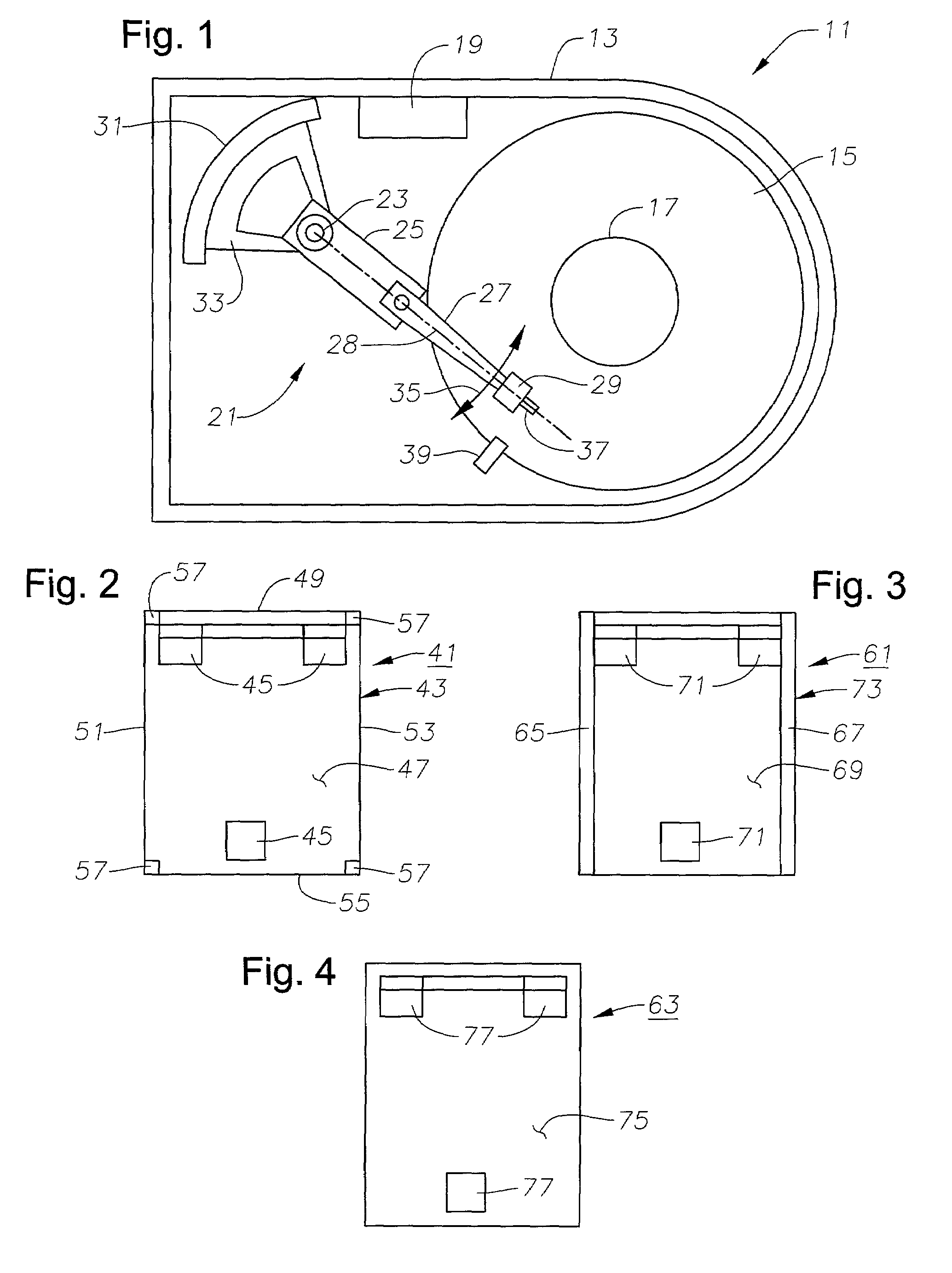
[0018]Referring to FIG. 1, a schematic drawing of one embodiment of an information storage system comprising a magnetic hard disk file or drive 11 for a computer system is shown. Drive 11 has an outer housing or base 13 containing a plurality of stacked, parallel magnetic disks 15 (one shown) which are closely spaced apart. Disks 15 are rotated by a spindle motor located therebelow about a central drive hub 17. An actuator 21 comprises a plurality of stacked, parallel actuator arms 25 (one shown) in the form of a comb that is pivotally mounted to base 13 about a pivot assembly 23. A controller 19 is also mounted to base 13 for selectively moving the comb of arms 25 relative to disks 15.

[0019]In the embodiment shown, each arm 25 has extending from it a pair of parallel, cantilevered load beams or suspensions 27 with a longitudinal axis 28. A head gimbal assembly 29 having at least one magnetic read / write head mounted on a slider is secured to a flexure that is flexibly mounted to eac...


PUM

PropertyMeasurementUnit
etch depthsaaaaaaaaaa
distanceaaaaaaaaaa
heightaaaaaaaaaa

Abstract

A slider in a disk drive is shock-protected with an overcoat layer of either metal or polymer directly on the areas of the slider that are prone to contact the disk when the slider is loaded off the platform, or when the slider is shocked while in operation over the data zone of the disk. The material used to form the layer absorbs shock and reduces wear, and is bonded or sputtered to the head in a region other than the pads of the air bearing surface. This region is typically the reactive ion etched (RIE) surface area and is slightly below the pads of the air bearing surface of the head. In an alternate version of the invention, the slider is protected by covering only the edges of the slider with a suitable material. Finally, the entire slider may be encased with the overcoating except for the pads of the air bearing surface.

Description

BACKGROUND OF THE INVENTION[0001]1. Technical Field[0002]The present invention relates in general to an improved disk drive, and in particular to an improved apparatus and method for protecting disks in a disk drive from head shock-induced errors and damage.[0003]2. Description of the Related Art[0004]Generally, a data access and storage system consists of one or more storage devices that store data on magnetic or optical storage media. For example, a magnetic storage device is known as a direct access storage device (DASD) or a hard disk drive (HDD) and includes one or more disks and a disk controller to manage local operations concerning the disks. Disks are rigid platters that are usually made of aluminum alloy or a mixture of glass and ceramic, and are covered with a magnetic coating. Typically, two or three disks are stacked vertically on a common spindle that is turned by a disk drive motor at several thousand revolutions per minute (rpm).[0005]The only other moving part withi...

Claims


Application Information

Patent Timeline
Patent Type & Authority Patents(United States)
IPC IPC(8): G11B5/60G11B21/21
CPCG11B21/21G11B5/6005G11B5/3106G11B5/40G11B5/6082
Inventor FELISS, NORBERT A.HUANG, YIYUNLU, JENNIFERTANG, WING TSANG
Owner WESTERN DIGITAL TECH INC
Why Eureka
Try Eureka