Surface Particle Counter

a particle counter and surface technology, applied in the field of scanners, can solve the problems of particle loss, particle transport from the surface to the particle counter, inaccurate readings of the particle counter, etc., and achieve the effect of vastly improving the overall efficiency of the particle-counting device and eliminating a number of steps

Active Publication Date: 2009-02-26
LIGHTHOUSE WORLDWIDE SOLUTIONS
View PDF6 Cites 6 Cited by
  • Summary
  • Abstract
  • Description
  • Claims
  • Application Information

AI Technical Summary

Benefits of technology

[0008]The present invention combines a scanner and a particle sensor or counter into varying types of particle-counting devices. The present invention eliminates a number of steps in the typical process. Because the present invention features a scanner combined with a counter, the overall efficiency of the particle-counting device is vastly improved. This is because combining the two elements together into the present invention eliminates particle traps and particle loss due to transport from the scanner to counter.

Problems solved by technology

One of the problems with this mechanism is the transport of particles from the surface to the particle counter.
Because of the distance between the surface of interest and the particle sensor, there are particle transport issues that may result in loss of particles in such problematic manners as particles sticking to the transport tube and particle traps caused by gaps and dead space of the various fittings.
This results in inaccurate readings from the particle counter.
This problem becomes greater as the particle size increases.

Method used


Image

  • Surface Particle Counter
  • Surface Particle Counter
  • Surface Particle Counter

Examples


Embodiment Construction

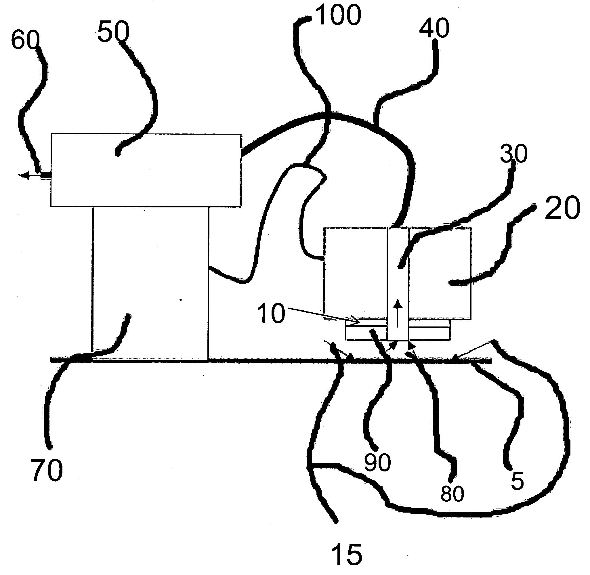
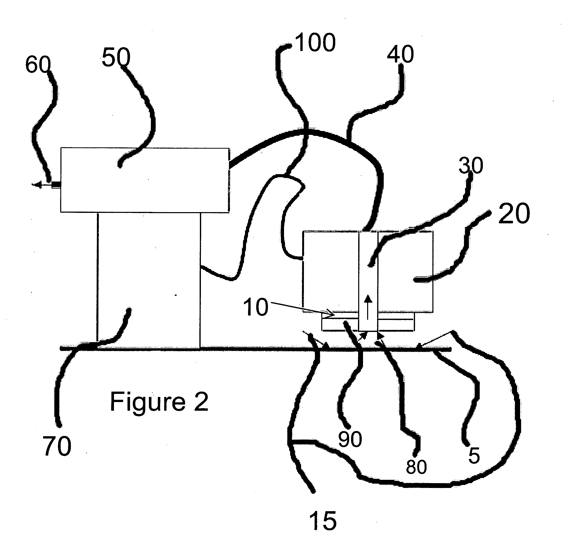
[0013]In FIG. 2, we see an environmental view of the present invention. In this view, we see that the scanner (10) is attached to the particle sensor (20). With the particle conduit (30) burrowed in between the scanner (10) and the particle sensor (20), both elements can remain attached surrounding the particle conduit (30) while eliminating particle traps and other elements that would otherwise cause particles to be lost during transfer.

[0014]In FIG. 2, we see that the scanner (10) and the particle sensor (20) are raised slightly above the surface (5). When the present invention is activated, the stream of airflow (15) will pass through the channel (80) that effectively separates the scanner (10) and particle sensor (20) from the surface (5). The channel (80) draws air from near the surface (5) in order to help avoid the problem of creating a vacuum between the scanner (10) and the surface (5).

[0015]Filters contained in the scanner head (90) operate to filter out the external air b...


PUM

PropertyMeasurementUnit
poweraaaaaaaaaa
areaaaaaaaaaaa
distanceaaaaaaaaaa

Abstract

A surface particle-counting device where the scanner element and the particle counting element have been combined so to reduce the number of lost particles and increase the overall efficiency of the particle-counting device. By removing the conventional tube that connects the scanner element and the particle counting element accuracy is increased.

Description

[0001]This is a non-provisional application claiming priority to provisional patent application No. 60 / 957,123 filed on Aug. 21, 2007.FIELD OF THE INVENTION [0002]The present invention relates to a scanner that is combined with a particle sensor for an improved and more efficient surface particle-counting device.BACKGROUND OF THE INVENTION [0003]Surface particle counters typically operate by using a scanner head that moves over the surface of the area of interest, pulling particles into the flow through a conduit. This conduit transports the particles to a counter. After being counted in the counter, the airflow is filtered and reutilized providing a stream of air in the scanner head meant to disturb the particles on the surface.[0004]Typically, prior inventions have a conduit separates the scanner and counter. Therefore, the typical process for a particle-counting device involves particles passing through a scanner where the particles are then pulled and transferred through a condu...

Claims


Application Information

Patent Timeline
Patent Type & Authority Applications(United States)
IPC IPC(8): G01N21/84
CPCG01N2015/0693G01N1/24
Inventor POCHY, ROCCO
Owner LIGHTHOUSE WORLDWIDE SOLUTIONS
Why Eureka
Try Eureka