Operating unit for optical imaging devices

a technology of optical imaging and operating unit, which is applied in the direction of optics, microscopes, instruments, etc., can solve the problems of operator-controlled elements, operator-controlled devices that do not provide feedback, and the complexity of apparatuses is relatively large, and achieve the effect of flexible use of imaging systems for operators

Active Publication Date: 2009-02-26
CARL ZEISS MICROSCOPY GMBH
View PDF7 Cites 9 Cited by
  • Summary
  • Abstract
  • Description
  • Claims
  • Application Information

AI Technical Summary

Benefits of technology

[0008]Starting from this state of the art, the object of the invention is based upon providing an operator-controlled device for optical imaging systems of the above-mentioned type to make possible a more flexible use of the imaging system for the operator.

Problems solved by technology

It is disadvantageous here that the configuration of the operator-controlled elements as well as their arrangement on the operator-controlled console do not correspond to the configuration and arrangement of the operator-controlled elements which are positioned directly on the imaging system.
However, these operator-controlled devices do not supply any feedback as to whether a set value, which is pregiven from the operator-controlled device, was actually adjusted on the microscope.
Furthermore, the apparatus complexity is relatively great because operator-controlled elements are there in duplicate, namely, on the imaging system itself and on the operator-controlled device.
Furthermore, the operator does not have the possibility, in accordance with his own judgment, to undertake adjusting options, which are selected with the same operator-controlled elements, either directly on the imaging system or from the operator-controlled device and to change this selection depending upon the object viewing task to be solved or to variably adapt the selection to his wishes.

Method used


Image

  • Operating unit for optical imaging devices
  • Operating unit for optical imaging devices
  • Operating unit for optical imaging devices

Examples


Embodiment Construction

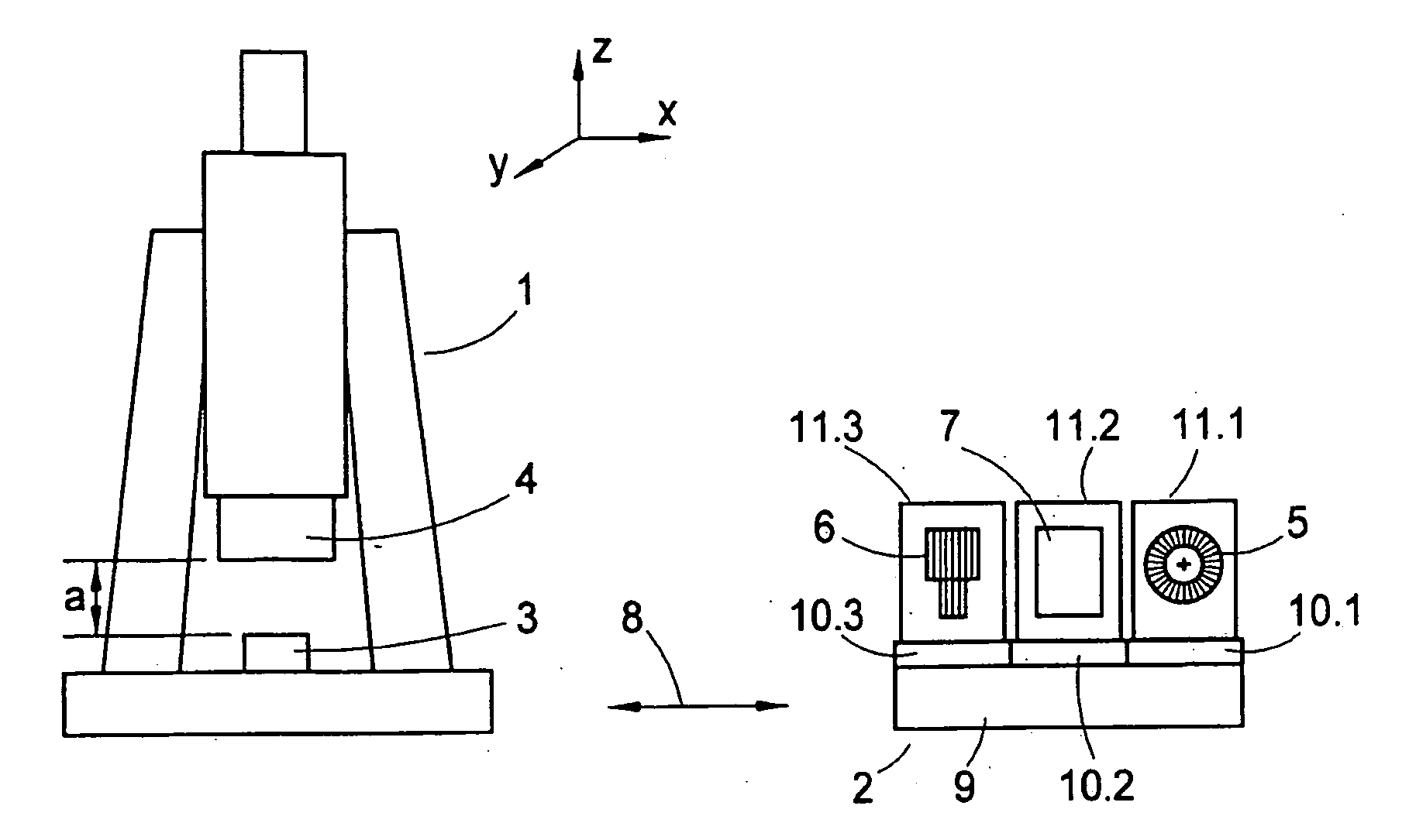
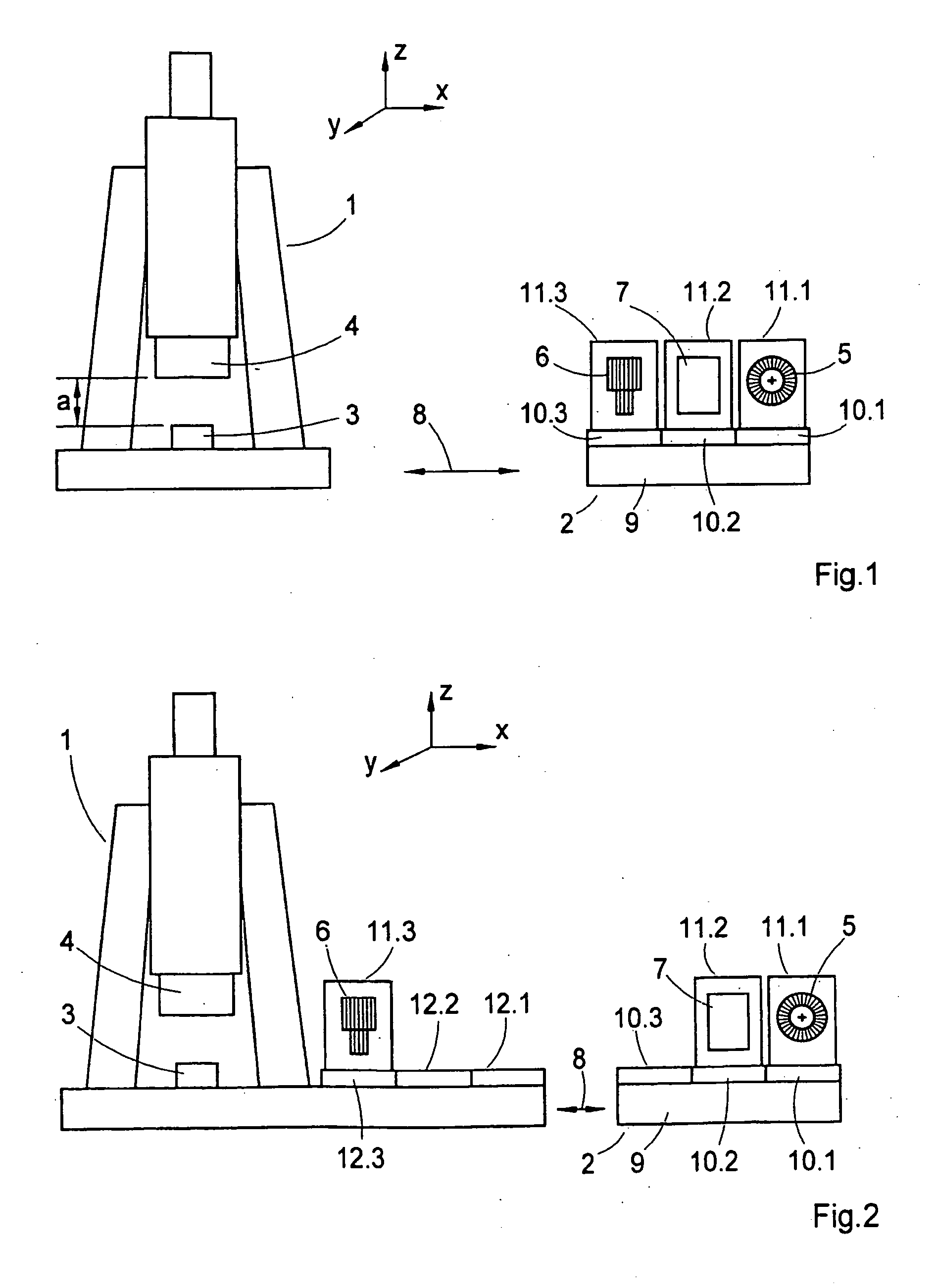
[0045]In FIG. 1, an imaging system in the form of a microscope 1 as well as a corresponding operator-controlled device 2 are shown. The schematic is simplified and serves to explain the functional principle.

[0046]The operator-controlled device 2 is provided for inputting adjustments which concern the imaging or viewing of an object 3. Such adjustments are to be undertaken at the microscope 1, for example, for focusing the image, changing the position of the object 3 relative to the objective 4 of the microscope 1 or also for adjusting the illuminating light emanating from an illuminating unit (not shown) and directed onto the object 3.

[0047]Operator-controlled elements are provided on the operator-controlled device 2 with which these adjustments can be inputted. Accordingly, for example, a rotation transducer 5 is provided with which the distance (a) between the object 3 and the objective 4 can be increased or decreased in the coordinate Z, that is, in the direction of the optical a...


PUM


Abstract

The invention relates to an operator-controlled device (2) for optical imaging systems, in particular for microscopes, equipped with operator-controlled elements (5, 6, 7) for inputting settings relating to the imaging of an object (3) to be observed. The operator-controlled device (2) further includes a display device for pregiven desired adjustment values and/or a display device for the actual adjustment values instantaneously achieved on the imaging system and transmitting devices for transmitting signals corresponding to the desired or actual adjustment values between the operator-controlled device (2) and the imaging system. The operator-controlled device includes: at least one modular component (11.1, 11.2, 11.3) with at least one operator-controlled element (5, 6, 7) for inputting desired adjustment values, a base component (9) designed for accommodating one or more such modular components (11.1, 11.2, 11.3) and arrangements for manually coupling the modular components (11.1, 11.2, 11.3) to the base component (9) and for manually separating the modular components (11.1, 11.2, 11.3) from the base component (9).

Description

CROSS REFERENCE TO RELATED APPLICATIONS[0001]This application is a continuation-in-part application of international patent application no. PCT / EP 2007 / 001643, filed Feb. 27, 2007, designating the United States and claiming priority from German application 10 2006 010 104.9, filed Feb. 28, 2006, the entire contents of which are incorporated herein by reference.FIELD OF THE INVENTION[0002]The invention relates to an operator-controlled device for optical imaging systems, especially for microscopes, which are equipped with operator-controlled elements for inputting settings which concern the imaging of an object to be viewed.BACKGROUND OF THE INVENTION[0003]The operator-controlled devices for optical imaging systems known from the state of the art can be subdivided into essentially two function groups.[0004]For example, operator-controlled consoles having operator-controlled elements belong to a first function group. From these operator-controlled consoles, control commands, which act...

Claims


Application Information

Patent Timeline
Patent Type & Authority Applications(United States)
IPC IPC(8): G02B21/06
CPCG02B21/24G02B21/368G02B21/365
Inventor WAGENER, MICHAELBELKNER, THOMAS
Owner CARL ZEISS MICROSCOPY GMBH
Why Eureka
Try Eureka