Spacial image display

Inactive Publication Date: 2009-02-26
SONY CORP
View PDF3 Cites 42 Cited by
  • Summary
  • Abstract
  • Description
  • Claims
  • Application Information

AI Technical Summary

Benefits of technology

[0036]When appropriate control is performed so that such predetermined expressions are satisfied, intensity variations in the brightness of a spacial image and color unevenness are prevented, and spacial image display is performed more favorably.
[0037]In the spacial image display according to the embodiment of the invention, the two-dimensional display section including a plurality of pixels of p colors and the lenticular lens slanted with respect to a pixel array are appropriately combined to emit a plurality of light rays corresponding to a plurality of viewing angles into space by surface segmentation, and relative positional relationship between each cylindrical lens of the lenticular lens and each pixel of the two-dimensional display section is periodically changed to periodically displace the emission direction of display image light from each pixel via each cylindrica

Problems solved by technology

However, in a spacial image display using a time division system in related arts, there is an issue that it is difficult to achieve a large-area display in terms of costs and manufacturing aptitude.
Moreover, there is an issue that, for example, in the case where a deflection micromirror array is used, to precisely deflect all micromirrors in synchronization with one another, it is necessary to independently control the micromirrors with high precision, but it is difficult to control the micromirrors.
Moreover, th

Method used


Image

  • Spacial image display
  • Spacial image display
  • Spacial image display

Examples


first embodiment

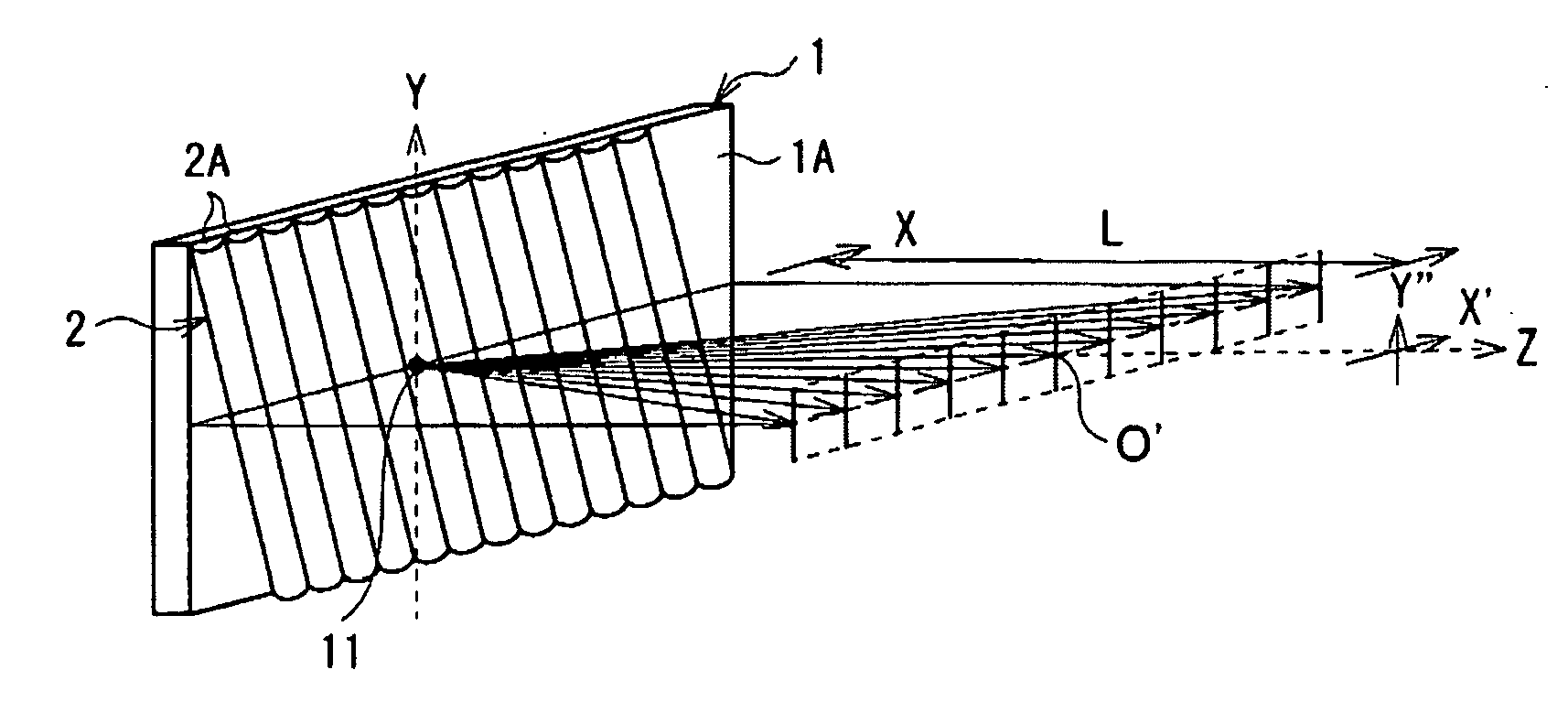
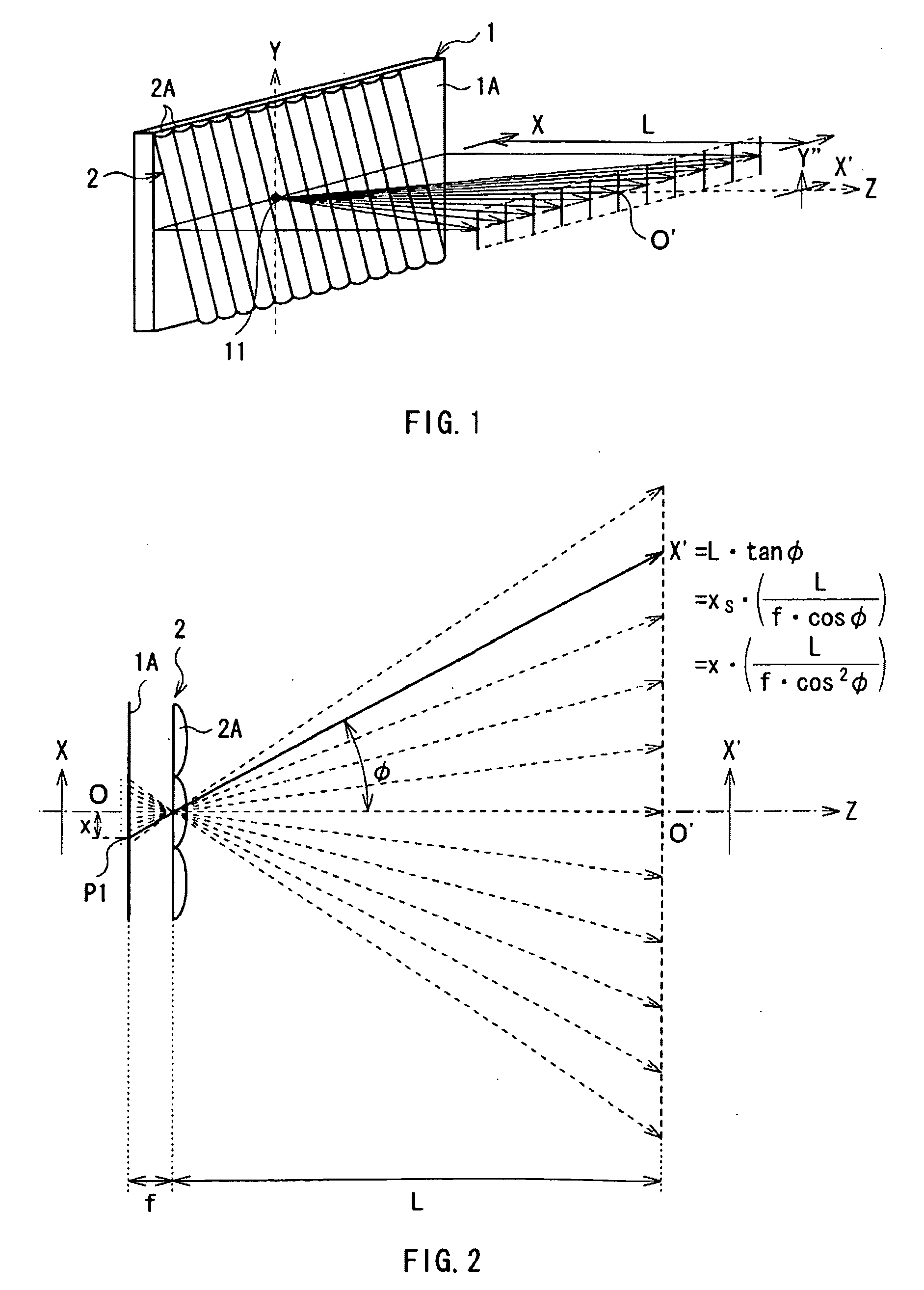
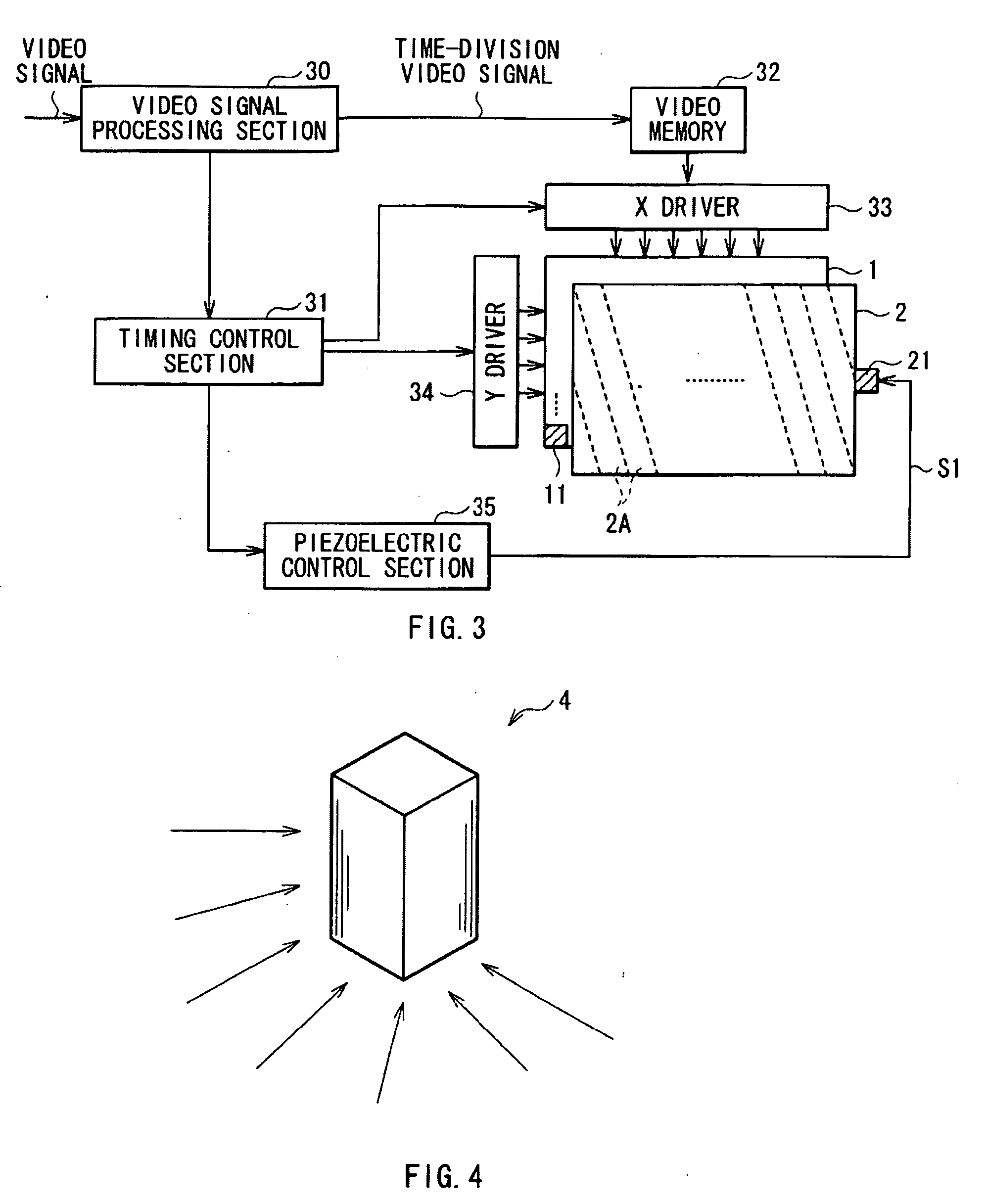
[0059]FIG. 1 shows an external view of a schematic configuration of a spacial image display according to a first embodiment of the invention. FIG. 1 also shows a state of light rays emitted from a pixel (a three-dimensional pixel 11). FIG. 2 shows the state of the light rays when viewed from above. FIG. 3 shows the whole configuration of the spacial image display including circuit elements according to the embodiment.

[0060]The spacial image display according to the embodiment includes a two-dimensional display and a lenticular lens 2. The two-dimensional display includes, for example, a two-dimensional display section 1 configured of a display device such as a liquid crystal display panel. The lenticular lens 2 includes a plurality of cylindrical lenses 2A arranged in parallel so that the cylindrical axes thereof are substantially parallel to one another, and has a plate shape as a whole. The lenticular lens 2 faces a display surface 1A of the two-dimensional display section 1 so th...

second embodiment

[0129]Next, a second embodiment of the invention will be described below. Like components are denoted by like numerals as of the first embodiment, and will not be further described.

[0130]In the first embodiment, it is obvious from the example shown in FIG. 14 that the pixels 10 of all kinds, that is, R, G and B are arranged in order in a focused position in the three-dimensional pixel 11 by the scanning operation (an operation of changing the relative positional relationship), color unevenness is prevented. On the other hand, FIGS. 18A and 18B show display examples in a spacial image display according to the embodiment. The spacial image display according to the embodiment has the same basic configuration as that of the spacial image display according to the first embodiment, except that the system of scanning operation is different.

[0131]In the embodiment, two states shown in FIGS. 18A and 18B constitute one three-dimensional frame. When a part where the deflection angle is φa is f...


PUM


Abstract

When a two-dimensional display section including a plurality of pixels of p colors and a lenticular lens slanted with respect to a pixel array are combined to emit a plurality of light rays corresponding to a plurality of viewing angles into space by surface segmentation at the same time. Moreover, relative positional relationship between each cylindrical lens and each pixel of the two-dimensional display section is periodically changed to periodically displace the emission direction of display image light from each pixel via each cylindrical lens. Images corresponding to a unit frame of a three-dimensional image are time-divisionally displayed on the two-dimensional section, and a timing of time-divisional display in the two-dimensional display section 1 and a timing for changing relative positional relationship are synchronously controlled. Thereby, stereoscopic display with higher definition using a combination of a surface segmentation system and a time-division system is performed.

Description

CROSS REFERENCES TO RELATED APPLICATIONS[0001]The present invention contains subject matter related to Japanese Patent Application JP 2007-216399 filed in the Japanese Patent Office on Aug. 22, 2007, the entire contents of which being incorporated herein by reference.BACKGROUND OF THE INVENTION[0002]1. Field of the Invention[0003]The present invention relates to an apparatus performing three-dimensional display by displaying a spacial image, in particular to a spacial image display including at least a two-dimensional display and a lenticular lens.[0004]2. Description of the Related Art[0005]Binocular stereoscopic displays which achieve a stereoscopic vision by displaying images with parallax to both eyes of a viewer have been known. On the other hand, as human stereoscopic perception functions, four functions, that is, binocular disparity, convergence, physiological accommodation and motion parallax are known; however, in the binocular stereoscopic displays, binocular disparity is ...

Claims


Application Information

Patent Timeline
IPC IPC(8): G02B27/22G02B30/29
CPCG02B27/225G02B27/2214G02B30/29G02F1/1335H04N13/00G02B30/00G02B30/27
Inventor YAMADA, MASAHIROAOKI, SUNAO
Owner SONY CORP
Why Eureka
Try Eureka