
Needle device having slideable member providing enhanced safety

a technology of safety and a slide, applied in the field of medical devices, can solve the problems of reducing the likelihood that medical personnel will suffer injury from the needle, and achieve the effects of reducing the likelihood, reducing the possibility of injury, and improving user safety

Inactive Publication Date: 2009-02-26
REID ALAN
View PDF15 Cites 2 Cited by
  • Summary
  • Abstract
  • Description
  • Claims
  • Application Information

AI Technical Summary

Benefits of technology

[0008]The present invention provides a medical device, such as a Huber needle, having a needle and a structure that enhances user safety during removal of the needle from a patient. The inventive structure reduces the likelihood that medical personnel will suffer injury from the needle as it is forcibly removed from the patient. While the invention is primarily shown and described in conjunction with a Huber-type needle, it is understood that the invention is applicable to devices in general in which it is desirable to reduce the possibility of injury from a needle.
[0009]In one aspect of the invention, a medical device includes a central structural member from which a needle extends. At least one wing portion extends from the central structural member for facilitating removal of the needle from the patient in a controlled manner. A base member for contacting the patient's skin is coupled to the central structural member. First and second members are pivotably secured to the base member so as to provide a structure that can be transitioned from a use position in which the needle extends from the device for insertion into the patient and a non-use position in which the needle is captured by the first member as the needle is extracted from the patient.
[0010]With this arrangement, an operator leverages pressure applied to the wing portion(s) with a finger (s) and counter pressure on the first member so as to enable a controlled removal of the needle from the patient. In addition, the collapsible / expandable structure captures the needle in the first member as it is removed from the patient to enhance operator safety.

Problems solved by technology

The inventive structure reduces the likelihood that medical personnel will suffer injury from the needle as it is forcibly removed from the patient.

Method used


Image

  • Needle device having slideable member providing enhanced safety
  • Needle device having slideable member providing enhanced safety
  • Needle device having slideable member providing enhanced safety

Examples


Embodiment Construction

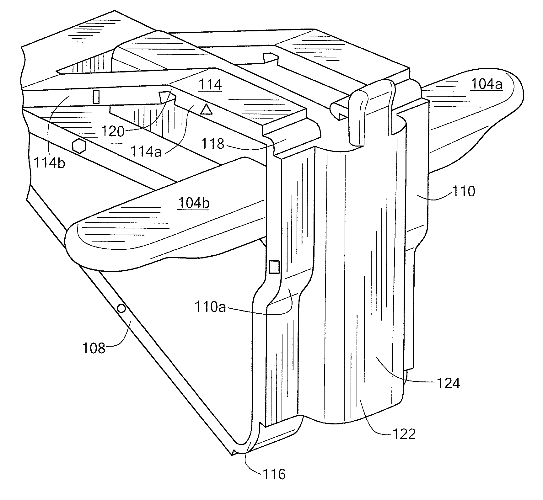
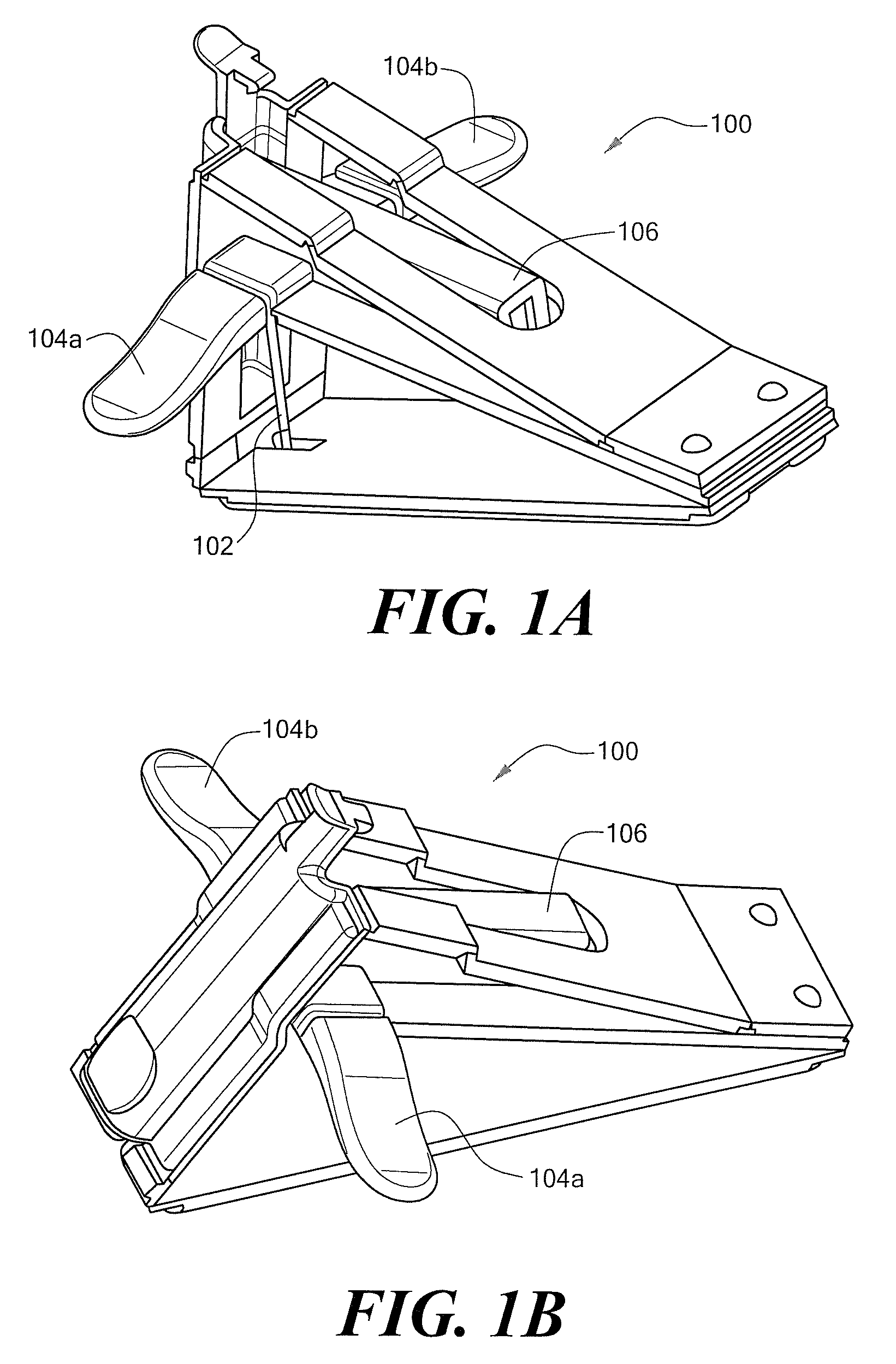
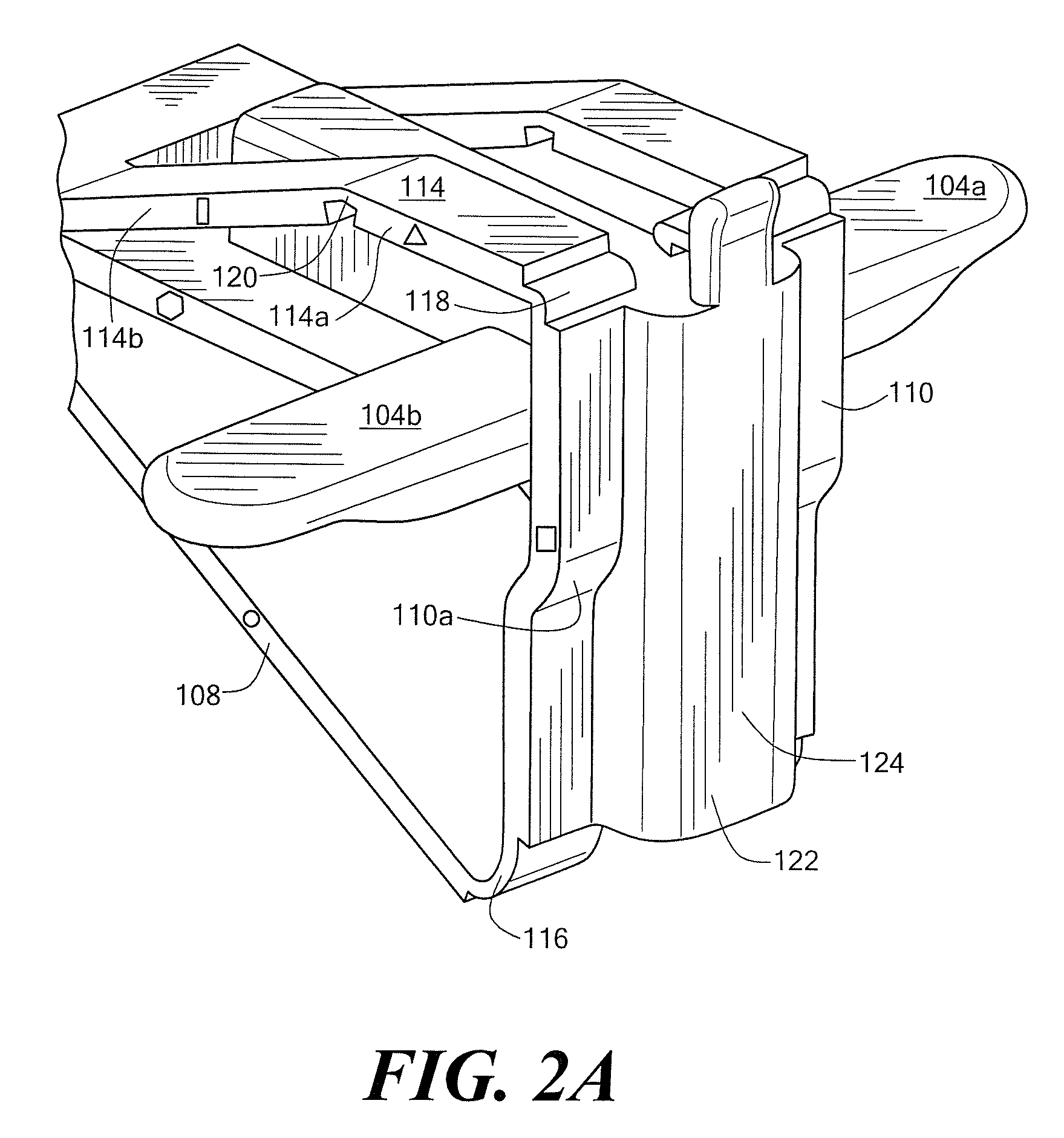
[0032]FIGS. 1A-1B show a medical device 100 including a needle 102 and a structure for enhanced operator safety in accordance with the present invention. In general, the device structure facilitates removal of the needle from a patient and captures the needle as it is retracted from the patient's body. During use, the device is relatively flat or collapsed and the needle extends outwardly for insertion into an implanted port device, for example. After use, the device is transitioned to the non-use position in which the needle is captured within the device. As described below, the device can include various features to prevent a transition to the use position from the non-use position to preclude re-use of the device.

[0033]The device 100 includes opposed first and second wing portions 104,a,b extending from a central structural member 106. As described below, the wing portions 104 provide surfaces on which an operator can apply pressure to insert the device. This arrangement leverage...


PUM


Abstract

A medical device, such as a Huber-type device, includes a structure that enhances operator safety by reducing the likelihood that a needle will accidentally injure an operator. In one embodiment, the device includes a collapsible structure that can move from a use position to a non-use position. The device includes first and second wing portions and a channel for covering the needle as it is extracted from the patient. The structure enables the operator to leverage applied pressure for a smooth removal of the needle into the device for safe disposal.

Description

CROSS REFERENCE TO RELATED APPLICATIONS[0001]This application is a Continuation of and claims the benefit of U.S. patent application Ser. No. 10 / 712,600, filed Nov. 13, 2003, which is a Continuation-in-Part of Ser. No. 10 / 242,976, filed Sep. 13, 2002, which is hereby incorporated by reference.STATEMENT REGARDING FEDERALLY SPONSORED RESEARCH[0002]Not Applicable.FIELD OF THE INVENTION[0003]The present invention relates generally to medical devices and, more particularly, to medical devices having a needle for insertion into a patient.BACKGROUND OF THE INVENTION[0004]Medical devices for injecting fluids into a patient are well known in the art. One such type of device is generally referred to as implanted ports, which can be implanted subcutaneously in a patient. Various types of ports can be used to provide access to the peritoneal cavity, as well as the vascular, arterial, and epidural systems. The ports typically include a catheter for access to a large vein and a port body having a...

Claims


Application Information

Patent Timeline
Patent Type & Authority Applications(United States)
IPC IPC(8): A61M5/32A61M5/158A61M25/06
CPCA61M5/158A61M5/3243A61M2005/1583A61M25/0612A61M2005/1581A61M5/3275A61M5/1626
Inventor REID, ALAN
Owner REID ALAN
Learn More