Uterine Therapy Device and Method

a technology of uterine therapy and uterine vein, which is applied in the field of uterine therapy devices and methods, can solve the problems of later discrediting the use of steam for this purpos

Active Publication Date: 2009-02-26
AEGEA MEDICAL
View PDF100 Cites 32 Cited by
  • Summary
  • Abstract
  • Description
  • Claims
  • Application Information

AI Technical Summary

Benefits of technology

[0032]Some embodiments of the vapor delivery tool have a vapor exit port, in which case the vapor delivery mechanism may further have a vapor delivery tool warming circuit with a vapor flow path from the vapor source to a vapor exhaust without passing through the vapor delivery tool vapor exit port. In such embodiments, the vapor delivery mechanism may also have a vapor delivery tool connector, with the vapor delivery mechanism being configured to deliver vapor through the warming circuit automatically when the vapor delivery tool connector is connected to the vapor source. The vapor delivery mechanism may also have a vapor delivery actuator operatively connected to the vapor delivery tool and the vapor source to control delivery of vapor from the vapor source to a vapor delivery tool exit port and to direct vapor through the vapor delivery tool warming circuit.
[0033]Some embodiments of the vapor delivery tool have a plurality of vapor exit ports. In some of such embodiments, none of the vapor exit ports is at a distal tip of the vapor delivery tool. In some such embodiments, the plurality of exit ports include one or more exit ports on a longitudinal portion of the vapor delivery tool proximal to a distal tip of the vapor delivery tool. The vapor delivery tool may also include a movable member disposed within a vapor delivery tool lumen adjacent at least one exit port, the movable member being adapted to alter vapor flow through the at least one exit port in response to vapor flow through the vapor delivery tool.

Problems solved by technology

The use of steam for this purpose was later discredited, apparently due to patient morbidity and mortality.

Method used


Image

  • Uterine Therapy Device and Method
  • Uterine Therapy Device and Method
  • Uterine Therapy Device and Method

Examples


Embodiment Construction

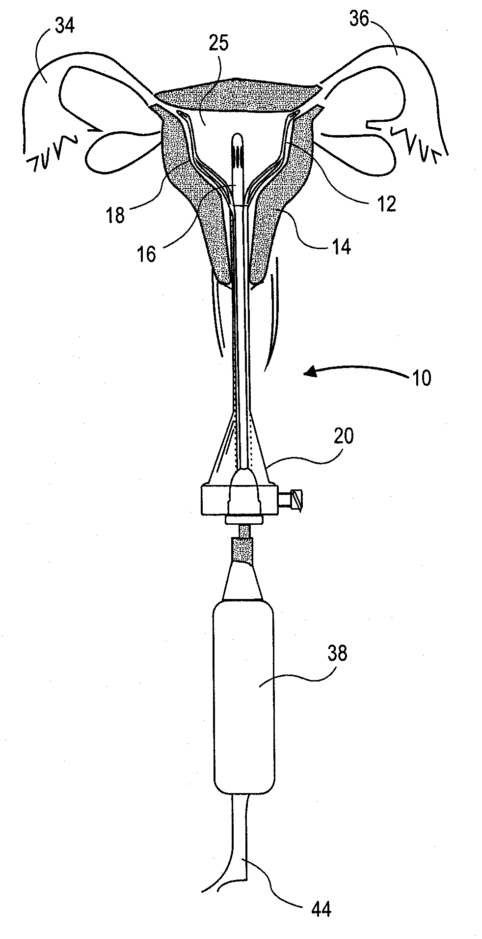
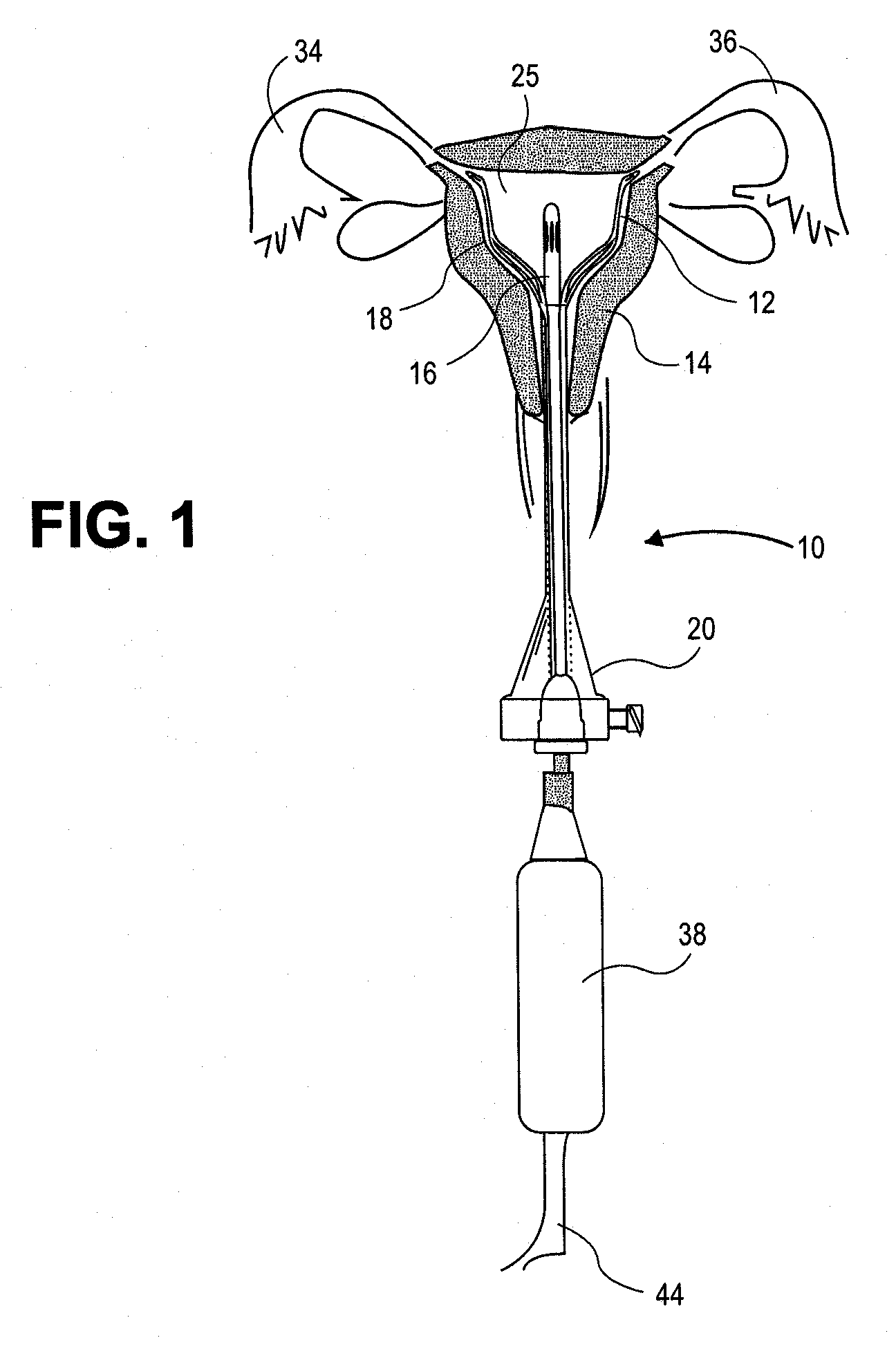
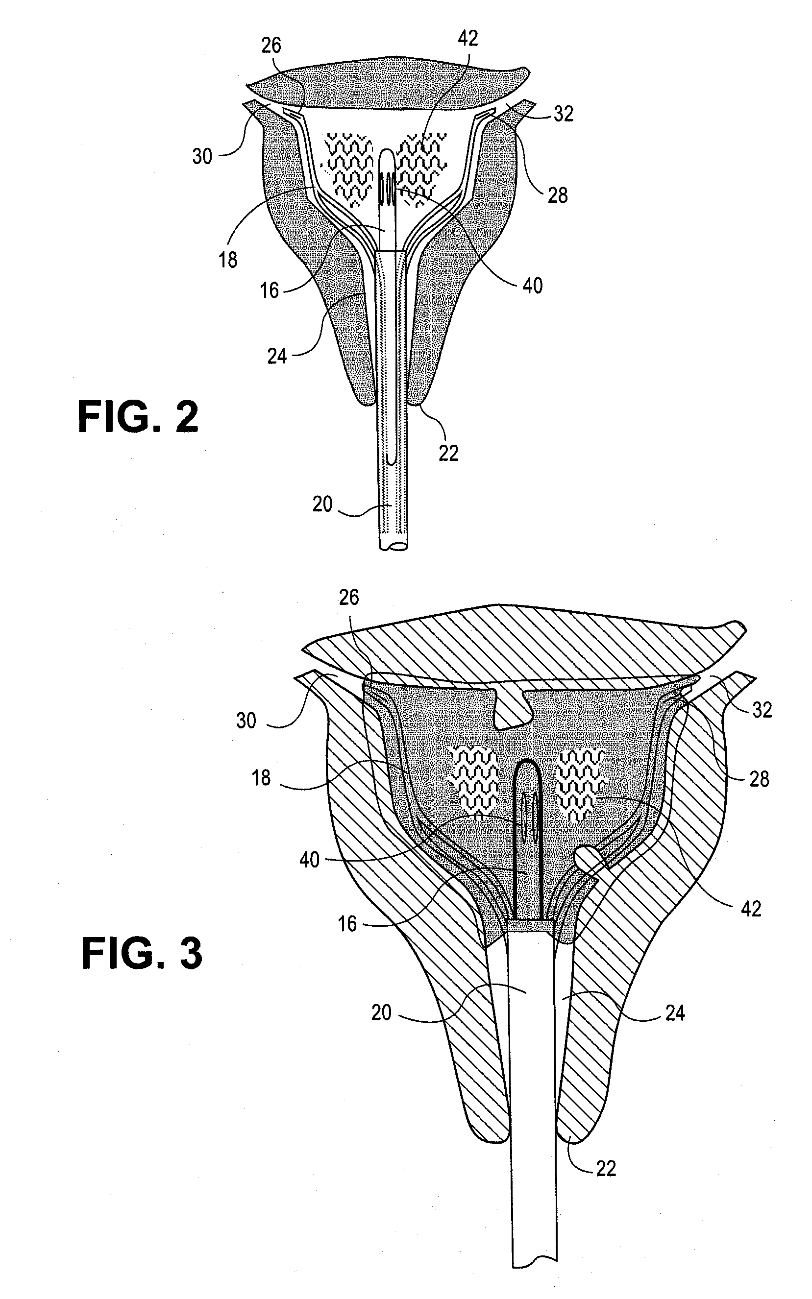
[0103]The present invention provides improved methods and apparatus for endometrial ablation using heated vapor.

[0104]FIGS. 1-45 show embodiments of a system 10 for heating and ablating the endometrium 12 of a uterus 14. In these embodiments, the system 10 includes a vapor delivery component or tool 16, a uterus expansion mechanism, such as basket 18, and an access tool or introducer 20. As shown in FIGS. 1-3, basket 18 and the distal end of the vapor delivery component 16 have been inserted through the cervical os 22 and cervical canal 24 into the lumen or cavity 25 of the uterus. Basket 18 has been expanded after insertion to open up the uterine cavity and to keep tissue away from the vapor outlets of the vapor delivery component. The distal ends 26 and 28 of basket 18 are disposed in the os 30 and 32 of the Fallopian tubes 34 and 36 to orient the device within the cavity and to help seal the Fallopian tube os. The basket struts 56 and 58 conform to any irregularities in the uteri...


PUM


Abstract

A method and system of providing therapy to a patient's uterus. The method include the following steps: inserting an access tool through a cervix and a cervical canal into the uterus; after inserting the access tool into the uterus, inserting a vapor delivery tool through an access tool lumen; delivering vapor through the vapor delivery tool into the uterus; and condensing the vapor on tissue within the uterus. The system has an access tool, the access tool being adapted to be inserted through a human cervical canal to place an opening of the access tool lumen within a uterus when the access tool is inserted through the cervical canal; and a vapor delivery mechanism, the vapor delivery mechanism having a vapor delivery tool and a vapor source, the vapor delivery tool being adapted to be inserted through the access tool to deliver condensable vapor from the vapor source to the uterus, the condensable vapor being adapted to condense within the uterus.

Description

CROSS REFERENCE TO RELATED APPLICATIONS[0001]This application claims the benefit under 35 U.S.C. § 119 of U.S. Provisional Application No. 60 / 957,626, filed Aug. 23, 2007, the disclosure of which is incorporated by reference as if fully set forth herein.[0002]This application is related to U.S. application Ser. No. ______[Atty Docket 10546-700.200], filed on the same day, entitled “Uterine Treatment Device and Method”; and to U.S. application Ser. No. ______[Atty Docket 10546-700.201], filed on the same day, entitled “Uterine Treatment Device and Method”; and to U.S. application Ser. No. ______[Atty Docket 10546-700.203], filed on the same day, entitled “Uterine Treatment Device and Method”, all of which are commonly owned.INCORPORATION BY REFERENCE[0003]All publications and patent applications mentioned in this specification are herein incorporated by reference to the same extent as if each individual publication or patent application was specifically and individually indicated to ...

Claims


Application Information

Patent Timeline
Patent Type & Authority Applications(United States)
IPC IPC(8): A61M31/00
CPCA61B18/04A61B2017/3425A61B2017/4216A61B2018/048A61B2018/00005A61B2018/00285A61B2018/00559A61B2017/4225
Inventor SHARKEY, HUGH R.REYES, RAMIROSPARKS, KURT D.
Owner AEGEA MEDICAL
Why Eureka
Try Eureka