Methods for treating the thoracic region of a patient's body

a thoracic region and spine technology, applied in the field of electrosurgery, can solve the problems of ineffective treatment, rf technique, and adjacent lesion to the probe tip, and achieve the effect of effective treatment, effective lesioning of the target nerve, and effective lesion

Active Publication Date: 2009-02-26
AVENT INC
View PDF101 Cites 134 Cited by
  • Summary
  • Abstract
  • Description
  • Claims
  • Application Information

AI Technical Summary

Benefits of technology

[0005]The course of the nerves in the thoracic spine varies considerably between individuals as well as between the different thoracic levels. Thus, in order to create an effective lesion, the electrosurgical device needs to be positioned to suit the varying anatomies. Embodiments of the present invention allow for effective treatment in the different thoracic levels. The use of cooling with standard RF allows the lesion to be formed substantially distal to the tip of the electrosurgical where the lesion forms between the electrosurgical device and the thoracic vertebra. This allows for effective lesioning of the target nerve when the electrosurgical device is positioned at a distance from the nerve. This ensures that when the probe is positioned near the course of the target nerve, the resulting lesion encompasses the target nerve. This provides an advantageous benefit not found in the prior art, in that it obviates the need for a probe to be placed in very close proximity to a target nerve in order to effectively lesion the target nerve. Thus, embodiments of the present invention are directed to a system and method for providing an effective treatment of a target nerve in the spine. More specifically, embodiments of the present invention are directed to treating the thoracic region of the spine.

Problems solved by technology

However, regardless of the approach used, a limitation of RF techniques is that the lesion forms immediately adjacent to the probe tip.
The treatment may be ineffective if the probe is positioned in the general area of the target nerve but not adjacent to the nerve.
(Neurosurgery, 20(4): 529-535, 1987) as the reason for low success rate of RF neurotomy in the spine, “despite the accurate placement of electrodes onto anatomically correct target points, the lesions may not fully incorporate the nerve.
However, RF electrodes coagulate circumferentially and only minimally distally, therefore the lesion may have been placed superficial to the nerve.” This problem is not limited to a perpendicular approach, as in the parallel approach even though “an electrode lying parallel to the nerve is more likely to incorporate the nerve .

Method used


Image

  • Methods for treating the thoracic region of a patient's body
  • Methods for treating the thoracic region of a patient's body
  • Methods for treating the thoracic region of a patient's body

Examples


Embodiment Construction

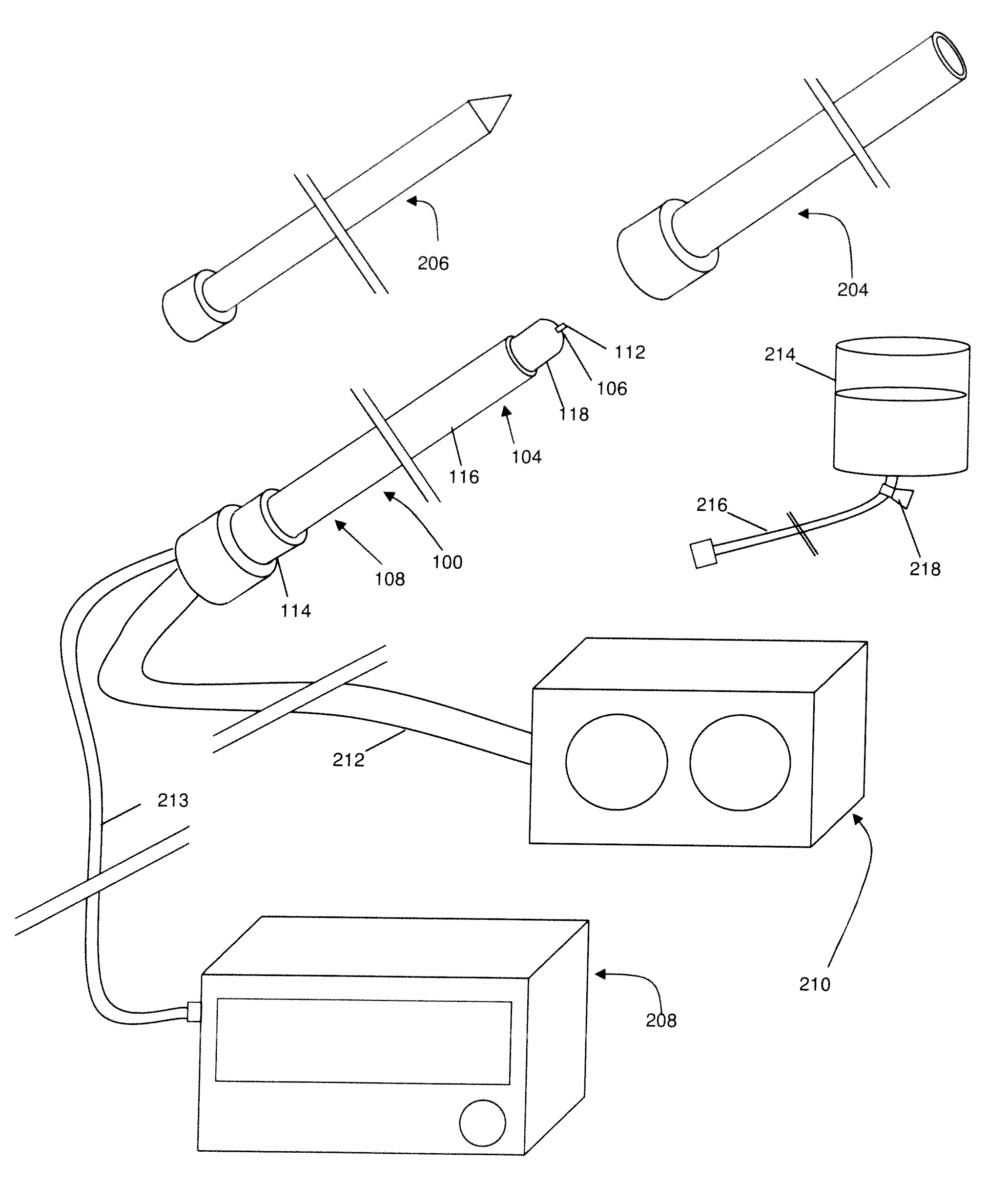
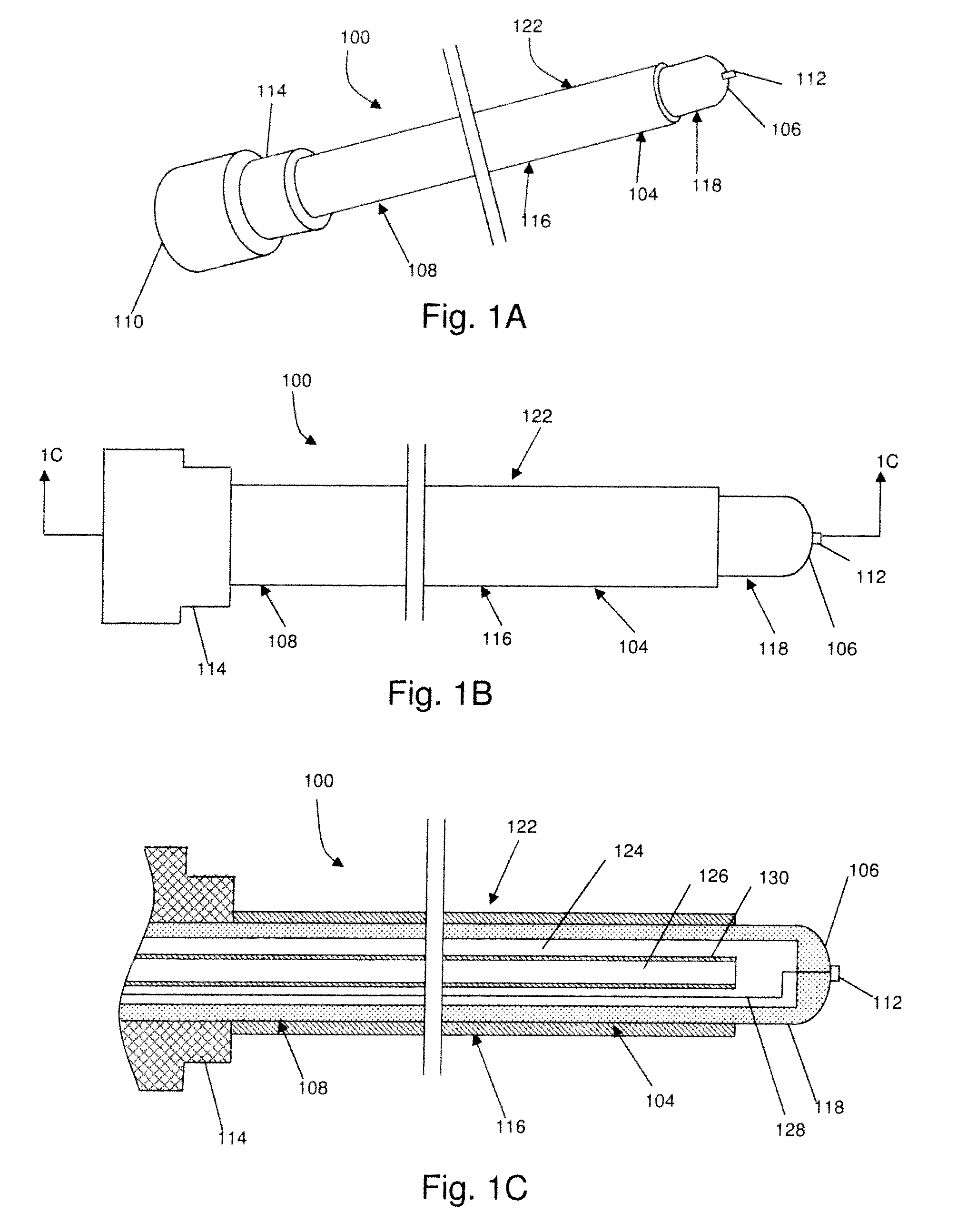
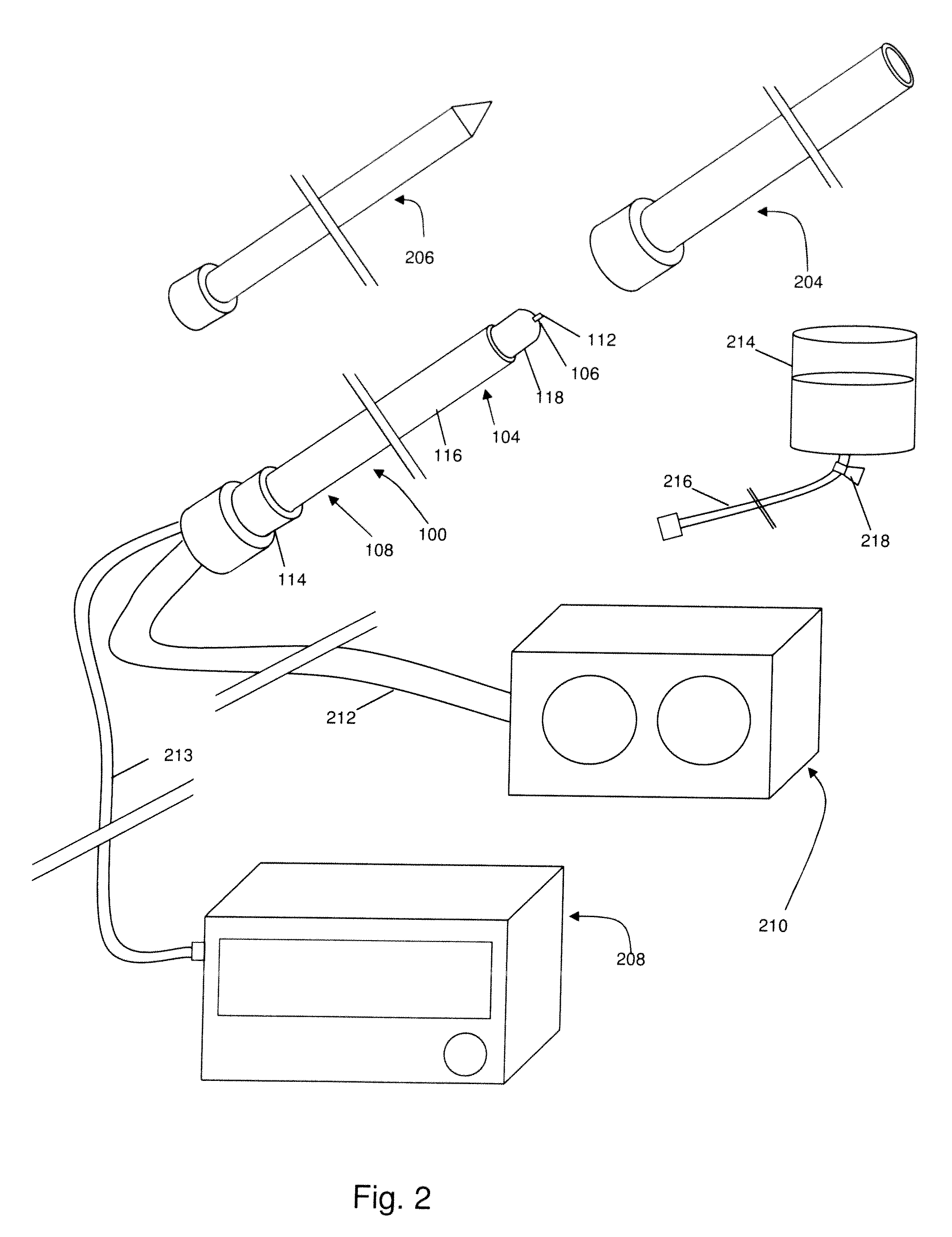
[0032]In one broad aspect, the present invention comprises a method for treating a thoracic region of a spine of a patient's body, for example in order to treat pain. Some embodiments of the method comprise positioning an energy delivery portion of an electrosurgical device to face a segment of a thoracic vertebra at a distance from the segment; and cooling the energy delivery portion and delivering energy through the energy delivery portion. As a feature of this aspect a lesion is formed at least substantially distal to the energy delivery portion. As another feature of this aspect a lesion is formed at a location at least between the energy delivery portion and the segment of the thoracic vertebra. In one feature of this aspect the energy delivery portion electrosurgical device may be inserted and positioned in a relatively safe, effective, and efficient manner. In one example, the energy delivery portion is positioned in proximity to a medial branch of a thoracic dorsal ramus ner...


PUM


Abstract

A method is disclosed for the treatment of a thoracic region of a patient's body. Embodiments of the method comprise positioning an energy delivery portion of an electrosurgical device to face a segment of a thoracic vertebra at a distance from the segment; and cooling the energy delivery portion and delivering energy through the energy delivery portion.

Description

CROSS REFERENCES TO RELATED APPLICATIONS[0001]This application is a continuation-in-part of U.S. patent application Ser. No. 12 / 176,035 (filed Jul. 18, 2008), which claims the benefit of U.S. Provisional Patent Application No. 60 / 950,706 (filed Aug. 19, 2007) and is a continuation-in-part of U.S. patent application Ser. No. 11 / 457,697 (filed Jul. 14, 2006). U.S. patent application Ser. No. 11 / 457,697 (filed Jul. 14, 2006) is a continuation-in-part of U.S. patent application Ser. Nos. 11 / 105,527 (filed Apr. 14, 2005), 11 / 105,490 (filed Apr. 14, 2005), and 11 / 105,524 (filed Apr. 14, 2005), all of which claim the benefit of U.S. Provisional Patent Application 60 / 604,348 (filed on Aug. 25, 2004), and are continuations-in-part of U.S. patent application Ser. No. 10 / 087,856 (tiled on Mar. 5, 2002), now U.S. Pat. No. 6,896,675. This application is also a continuation-in-part of U.S. patent application Ser. No. 11 / 381,783 (filed on May 5, 2006). This application is also a continuation-in-pa...

Claims


Application Information

Patent Timeline
Patent Type & Authority Applications(United States)
IPC IPC(8): A61H15/00A61B19/00A61B18/18
CPCA61B18/1482A61B2018/00023A61B2018/00083A61B2018/00196A61B2018/00434A61B2218/007A61B2018/00791A61B2018/1497A61B2019/464A61B2218/002A61B2018/0044A61B2090/064A61B18/148A61B2018/00815A61B2018/00821
Inventor LEFLER, AMYGODARA, NEILHARRISON, ROBERT
Owner AVENT INC
Why Eureka
Try Eureka