Liquid filter assembly; and methods

a technology of liquid filter and assembly, applied in the direction of filtration separation, machine/engine, separation process, etc., can solve problems such as downstream components being damaged

Active Publication Date: 2009-03-05
DONALDSON CO INC
View PDF11 Cites 63 Cited by
  • Summary
  • Abstract
  • Description
  • Claims
  • Application Information

AI Technical Summary

Benefits of technology

[0005]Liquid filter assemblies are provided. The liquid filter assemblies each, include a housing and a suction filter assembly. The housing defines an interior and includes a liquid flow inlet arrangement, a liquid flow outlet arrangement, and a tank reservoir liquid flow inlet/outlet. The suction filter assembly is secured to the housing and is positioned in liquid flow communication with the tank reservoir liquid flow inlet/outlet. The suction filter asse

Problems solved by technology

Conditions such as cold starts, flow surges or occlude

Method used


Image

  • Liquid filter assembly; and methods
  • Liquid filter assembly; and methods
  • Liquid filter assembly; and methods

Examples


first example embodiment

I. A First Example Embodiment; FIGS. 1-9

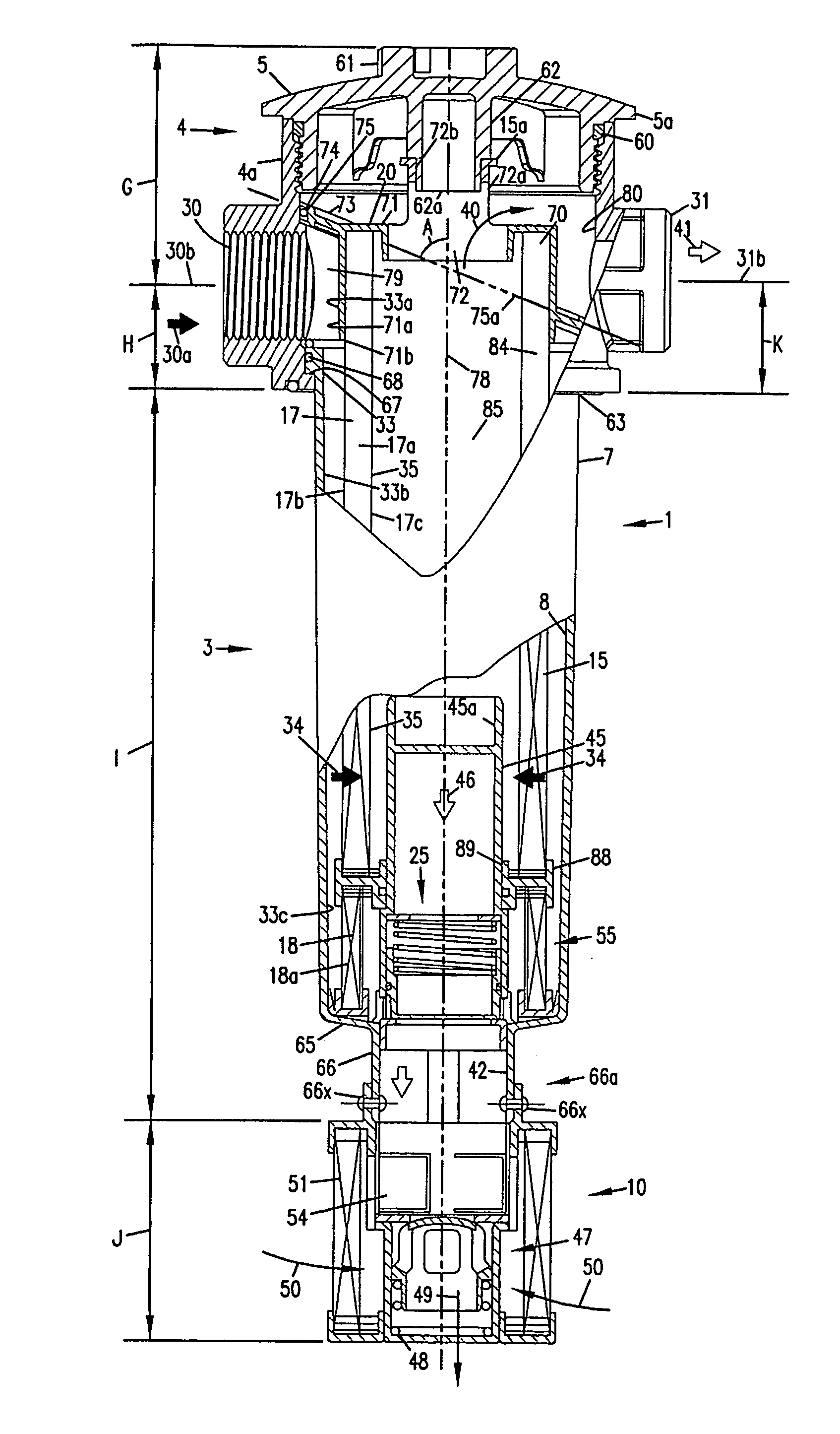
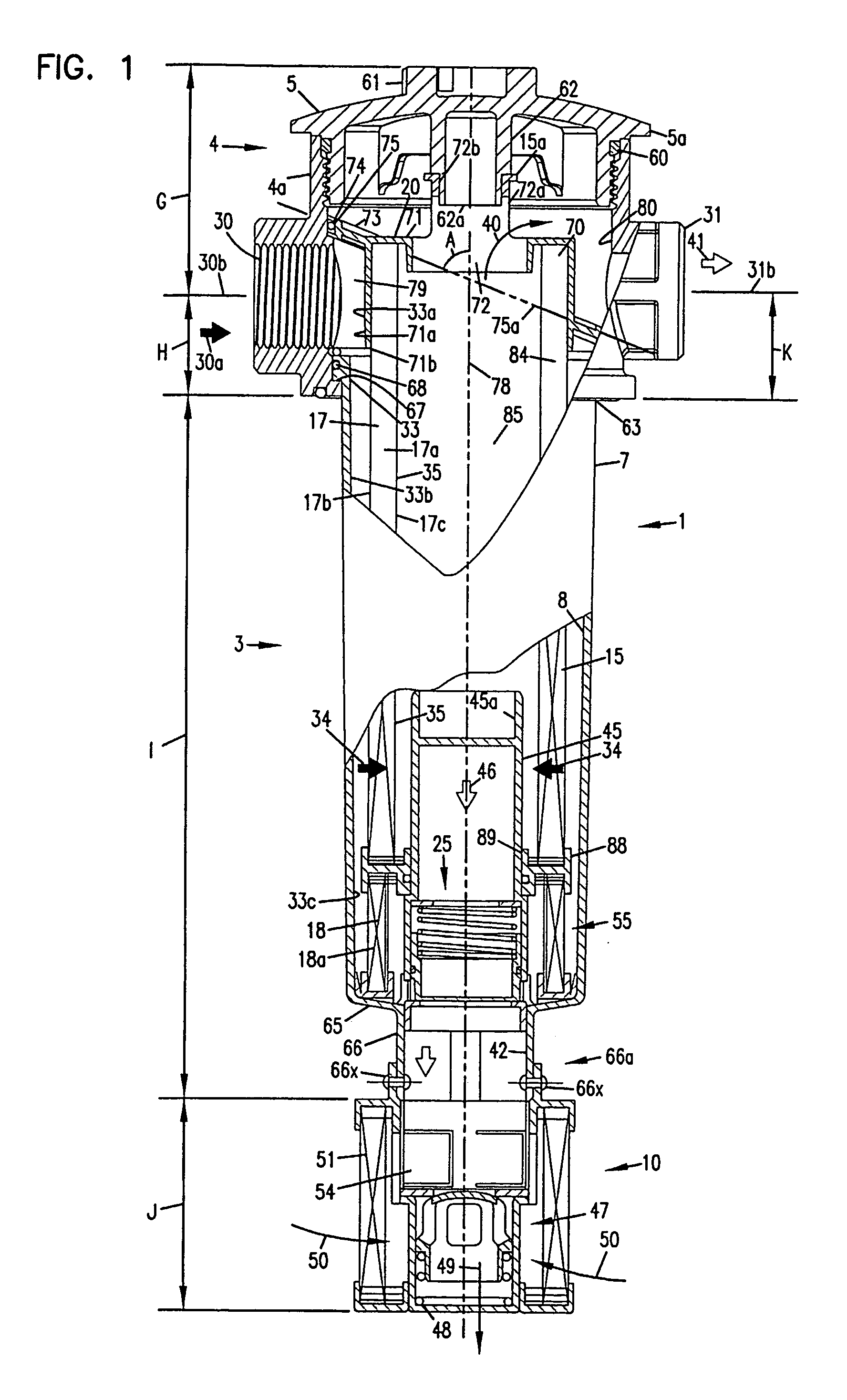
[0050]The reference numeral 1, FIG. 1, generally indicates a liquid filter arrangement or assembly according to one embodiment of the present disclosure. In FIG. 1, the assembly 1 is depicted in an ordinary orientation for use. Herein the terms “top,”“bottom,”“above,” and “below” are sometimes used to characterize the relative positions of components. When these terms are used, reference is meant to the orientation of FIG. 1, i.e., the typical orientation of use for the assembly 1.

[0051]The liquid filter assembly 1 includes a housing 3: comprising a filter head 4 having a body 4a and a removable top or cover 5; and, a side wall 7, which in use depends from filter head 4. In general, the housing 3 defines an internal volume 8, in which: selected internal componentry as defined is contained; and, certain filtering and flow operations, as described herein below, occur. The liquid filter assembly 1 further includes a suction filter assembly 10, as...

second embodiment

II. A Second Embodiment; FIGS. 10-29

[0157]The principles described generally above, can be applied in arrangements having alternate specific features, and configured for still further applications. In FIGS. 10-29 such an arrangement is depicted, for application in hydraulic systems with expected flow rates, for example, of up to about 250 liters per minute. Of course the principles could be applied, to construct arrangements to allow for alternate flow rates, if desired.

[0158]As will be apparent from the following descriptions, many of the features depicted have analogous functions and operate analogously to features described previously, in connection with FIGS. 1-9.

[0159]The reference numeral 601FIG. 10 generally indicates a liquid filter arrangement or assembly according to this aspect of the present disclosure. The liquid filter assembly 601 includes a housing 603 comprising a filter head 604 having a body 604a and a removable top or cover 605; and, a side wall 607, which in use...


PUM

PropertyMeasurementUnit
Pressureaaaaaaaaaa
Angleaaaaaaaaaa
Flow rateaaaaaaaaaa

Abstract

A liquid filter assembly is provided. The preferred assembly includes a serviceable filter cartridge having a primary filter section and a secondary or bypass filter section. The preferred assembly includes a bypass valve arrangement and a suction filter arrangement. The suction filter arrangement preferably includes a dimensionally biased valve arrangement, preferably one which is devoid of a helical coiled spring, to control flow through the suction filter. A flow/pressure regulation valve, to allow flow from an interior of the assembly to a reservoir if needed, is preferably provided. Preferred serviceable filter cartridges are shown.

Description

CROSS-REFERENCE TO RELATED APPLICATION[0001]The present application includes the content of, with edits, U.S. Provisional Application 60 / 532,761, filed Dec. 22, 2003. A claim to priority from U.S. Provisional 60 / 532,761 is made, to the extent appropriate. The complete disclosure of U.S. Provisional Application 60 / 532,761 is incorporated herein by reference.FIELD OF THE INVENTION[0002]The invention relates generally to liquid filters and methods. Example embodiments described, are in-tank filters, for use, for example, in a hydraulic system.BACKGROUND OF THE INVENTION[0003]Liquid filters are employed in a variety of applications, including, for example, hydraulic systems, fuel systems and engine lubrication systems.[0004]In general, liquid filters which accommodate downstream components, are of concern. Particularly, it is of concern to prevent cavitation of pumps and other equipment downstream from liquid filters. Conditions such as cold starts, flow surges or occluded elements can ...

Claims


Application Information

Patent Timeline
IPC IPC(8): B01D35/147B01D35/157B01D35/153B01D29/21B01D35/027
CPCB01D29/21B01D35/0276B01D2201/40B01D2201/34B01D2201/302B01D2201/296B01D2201/295B01D35/1576B01D35/1573B01D29/54B01D29/96B01D35/147B01D35/153B01D35/157B01D35/16B01D35/30
Inventor SCHIAVON, ANGELOCANTONI, MAUROZANETTIN, ANDREYFORMICA, CLAUDIO
Owner DONALDSON CO INC
Why Eureka
Try Eureka