Electric motor and an actuator having the same

a technology of electric motors and actuators, applied in the direction of dynamo-electric brake control, mechanical energy handling, mechanical equipment, etc., can solve the problems of small output torque of electric motors, drop in current of electric motors, and possible mechanical damage to drive components

Active Publication Date: 2009-03-05
DENSO CORP
View PDF23 Cites 27 Cited by
  • Summary
  • Abstract
  • Description
  • Claims
  • Application Information

AI Technical Summary

Problems solved by technology

When an excessive braking torque is generated in the electric motor, for example, at the time of locking of the drive subject, a mechanical damage may possibly be applied to components of the drive subject by an excessive rotational torque generated by the electric motor.
In such a case, the drive current of the electric motor drops, and the output torque of the electric motor becomes small.
Also, at the low battery voltage, the drive current drops, so that the output torque of the electric motor becomes small.
Thus, at the time of changing the shift range, the excessive rotational torque (excessive load) is not exerted on the rotor shaft of the electric motor independent of the temperature and the voltage.
However, when the drive subject is placed in the locked state under the condition of “low temp

Method used


Image

  • Electric motor and an actuator having the same
  • Electric motor and an actuator having the same
  • Electric motor and an actuator having the same

Examples


Embodiment Construction

[0025]Now, with reference to FIGS. 1A to 4, a shift range change apparatus according to an embodiment of the present invention will be described.

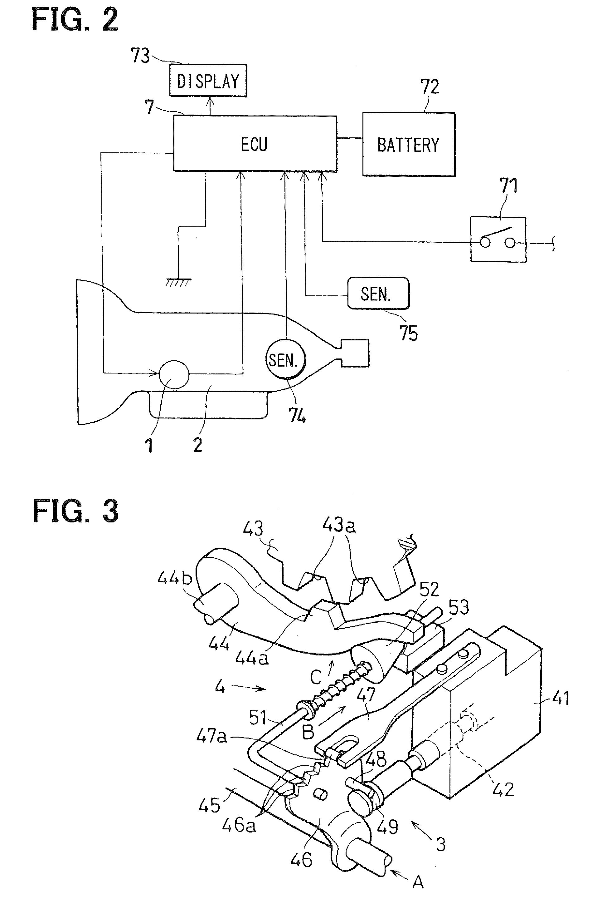
[0026]In the shift range change apparatus, an SBW actuator 1 (see FIGS. 1A and 1B) drives a shift range change mechanism 3 and a parking change mechanism 4 (see FIG. 3) to change an operational state thereof. These change mechanisms 3 and 4 are installed to an automatic transmission 2 (see FIG. 2), which changes a speed of a rotational output of a vehicle engine (which may be either an internal combustion engine alone or a hybrid of an internal combustion engine+an electric motor).

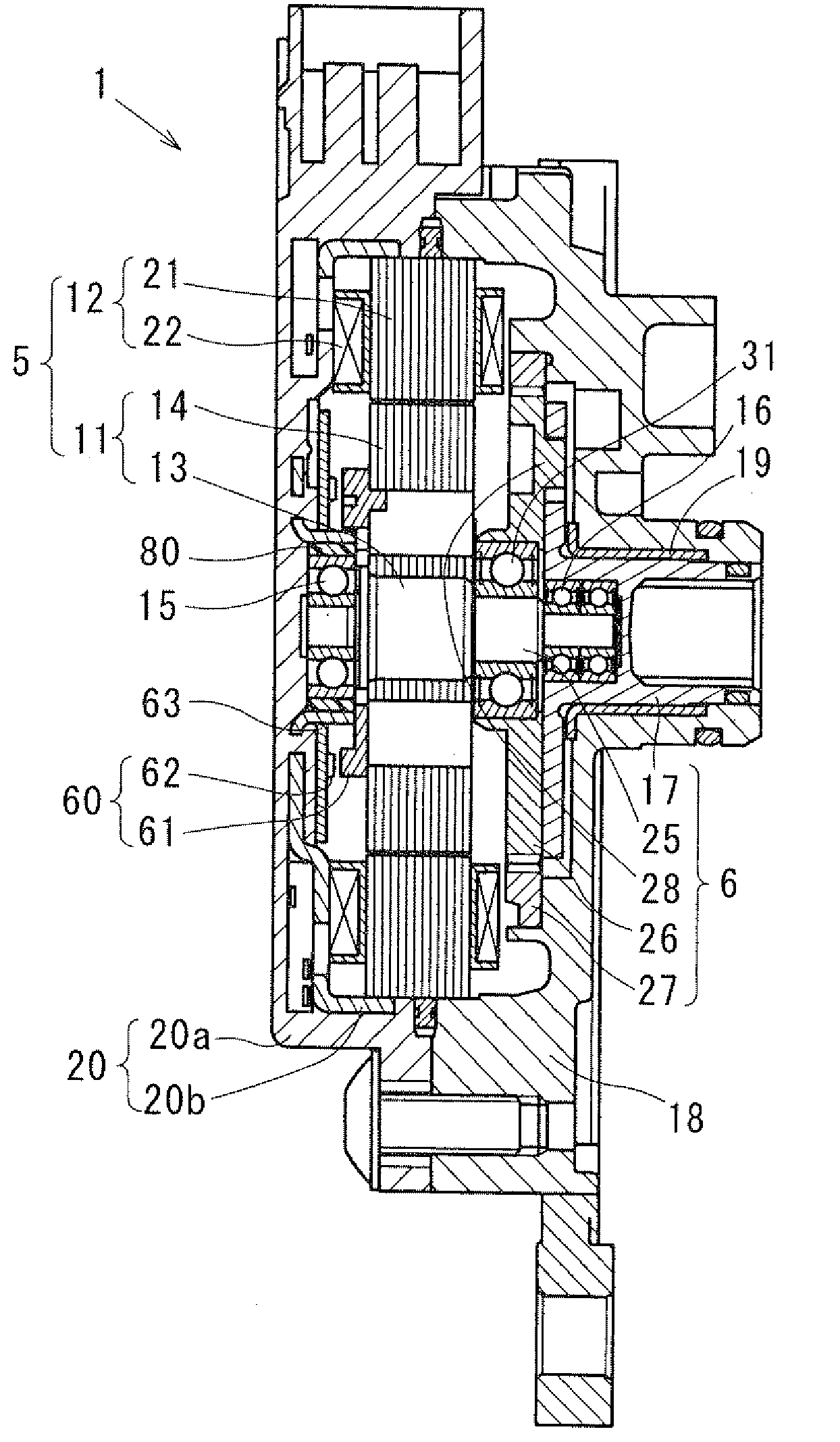
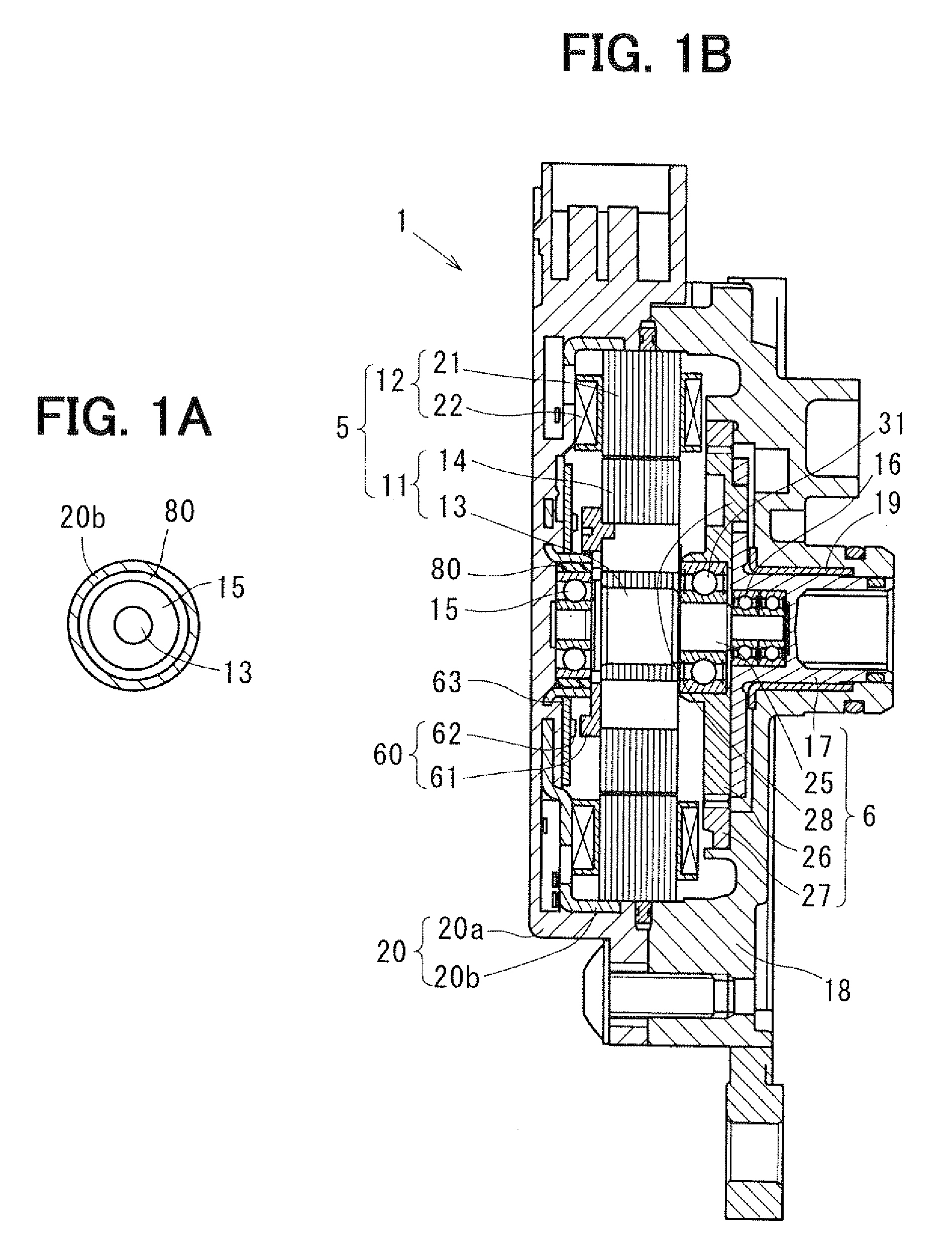
[0027]The SBW actuator 1 is a servo mechanism, which drives the shift range change mechanism 3 and the parking change mechanism 4. As shown in FIG. 1B, the SBW actuator 1 includes a synchronous electric motor 5 and a speed reducer 6. The speed reducer 6 reduces a rotational speed of rotation of the motor 5 and outputs the rotation of the reduced speed. The rotatio...


PUM


Abstract

In an electric motor of an SBW actuator, a rotor shaft is rotated upon energization of the motor. A rotor core is rotated integrally with the rotor shaft. A resilient member enables tilting or decentering of the rotor shaft upon application of a decentering force on the rotor shaft. A stator core contacts the rotor core when the rotor shaft is tilted or decentered.

Description

CROSS REFERENCE TO RELATED APPLICATION[0001]This application is based on and incorporates herein by reference Japanese Patent Application No. 2007-229365 filed on Sep. 4, 2007.BACKGROUND OF THE INVENTION[0002]1. Field of the Invention[0003]The present invention relates to an electric motor and an actuator having the same.[0004]2. Description of Related Art[0005]An electric motor, which drives a drive subject to rotate the same, is known.[0006]When an excessive braking torque is generated in the electric motor, for example, at the time of locking of the drive subject, a mechanical damage may possibly be applied to components of the drive subject by an excessive rotational torque generated by the electric motor.[0007]The above disadvantage will be illustrated by using an example of a shift range change apparatus of a shift-by-wire (SBW) type.[0008]An automatic transmission of a vehicle includes a shift range change mechanism (including a parking change mechanism) and is shifted manual...

Claims


Application Information

Patent Timeline
IPC IPC(8): H02P29/04H02K7/116
CPCF16H61/32H02K15/16H02K5/24H02K5/1732
Inventor KIMURA, KIYOSHIYOSHIYAMA, SHIGERU
Owner DENSO CORP
Why Eureka
Try Eureka