Debris shield for upper tie plate in a nuclear fuel bundle and method for filtering debris

Inactive Publication Date: 2009-03-05
GLOBAL NUCLEAR FUEL -- AMERICAS
View PDF31 Cites 25 Cited by
  • Summary
  • Abstract
  • Description
  • Claims
  • Application Information

AI Technical Summary

Benefits of technology

[0008]A method has been developed to prevent debris falling into a nuclear reactor fuel assembly including a bundle of fuel rods mounted below an upper tie plate and housed in a channel, the method comprising: inserting a debris shield which can be either a removable unit, or attached as a permanent integrated structure within the upper

Problems solved by technology

Debris may fall through a conventional upper tie-plate and become lodged within the fuel bundle where the debris may cause fuel rod fretting during normal BWR operating conditions.
Fretting is potentially damaging to the fuel rods, resulting in

Method used


Image

  • Debris shield for upper tie plate in a nuclear fuel bundle and method for filtering debris
  • Debris shield for upper tie plate in a nuclear fuel bundle and method for filtering debris
  • Debris shield for upper tie plate in a nuclear fuel bundle and method for filtering debris

Examples


third embodiment

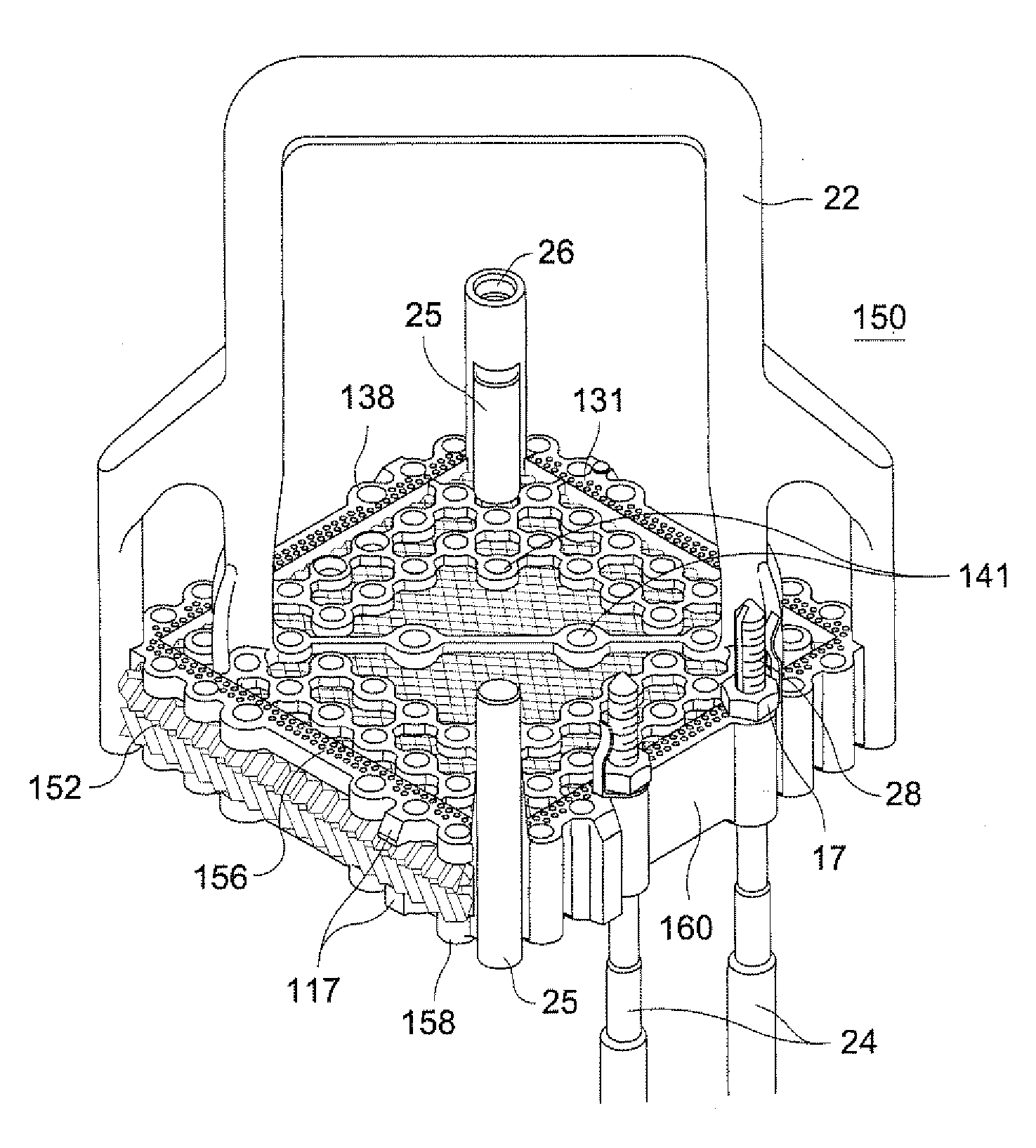
[0039]FIG. 9 shows an upper tie plate 150 having a removable debris shield 152 that slides in a slot 154 between an upper planar section 156 and a lower planar section 158 of the upper tie plate 150 that may be a removable unit or a permanent integrated structure in the upper tie plate. In FIG. 9, the debris shield is shown as being removed from the slot 154 of the upper tie plate. FIG. 10 shows the debris shield 152 fully inserted and secured within the upper tie plate 150. FIG. 11 is the side view of the debris filter 152 fully inserted into the upper tie plate cavity 154. FIGS. 12 and 13 show top and bottom views, respectively, of the upper tie plate 150.

[0040]A three-sided frame 160 of the upper tie plate 150 holds together the upper and lower planar sections 156, 158. The frame may be porous, e.g., have small vertical openings 131 to allow fluid to pass through the frame and block passage of debris. The openings in the frame increase the effective flow area of passages through ...

first embodiment

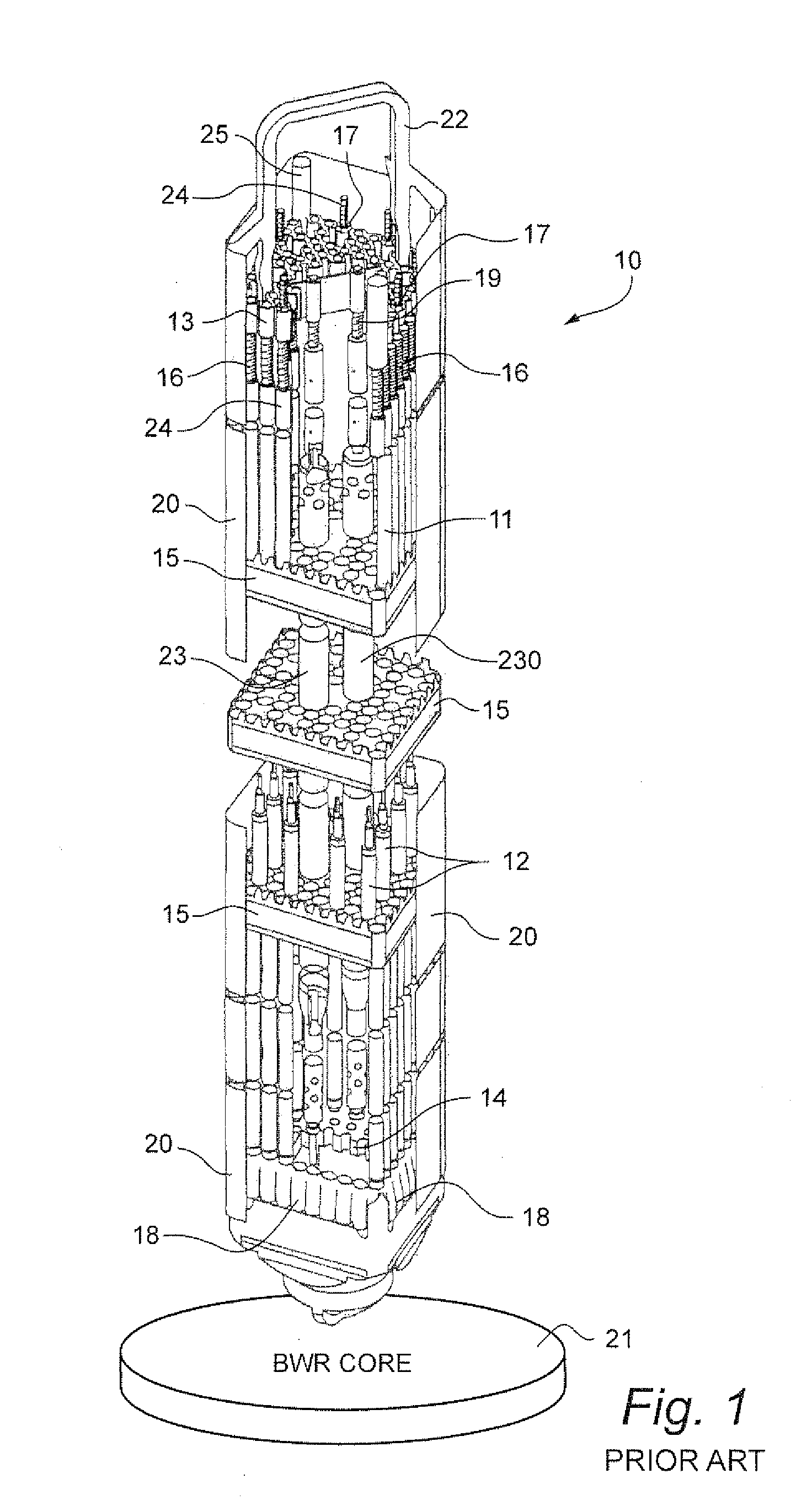
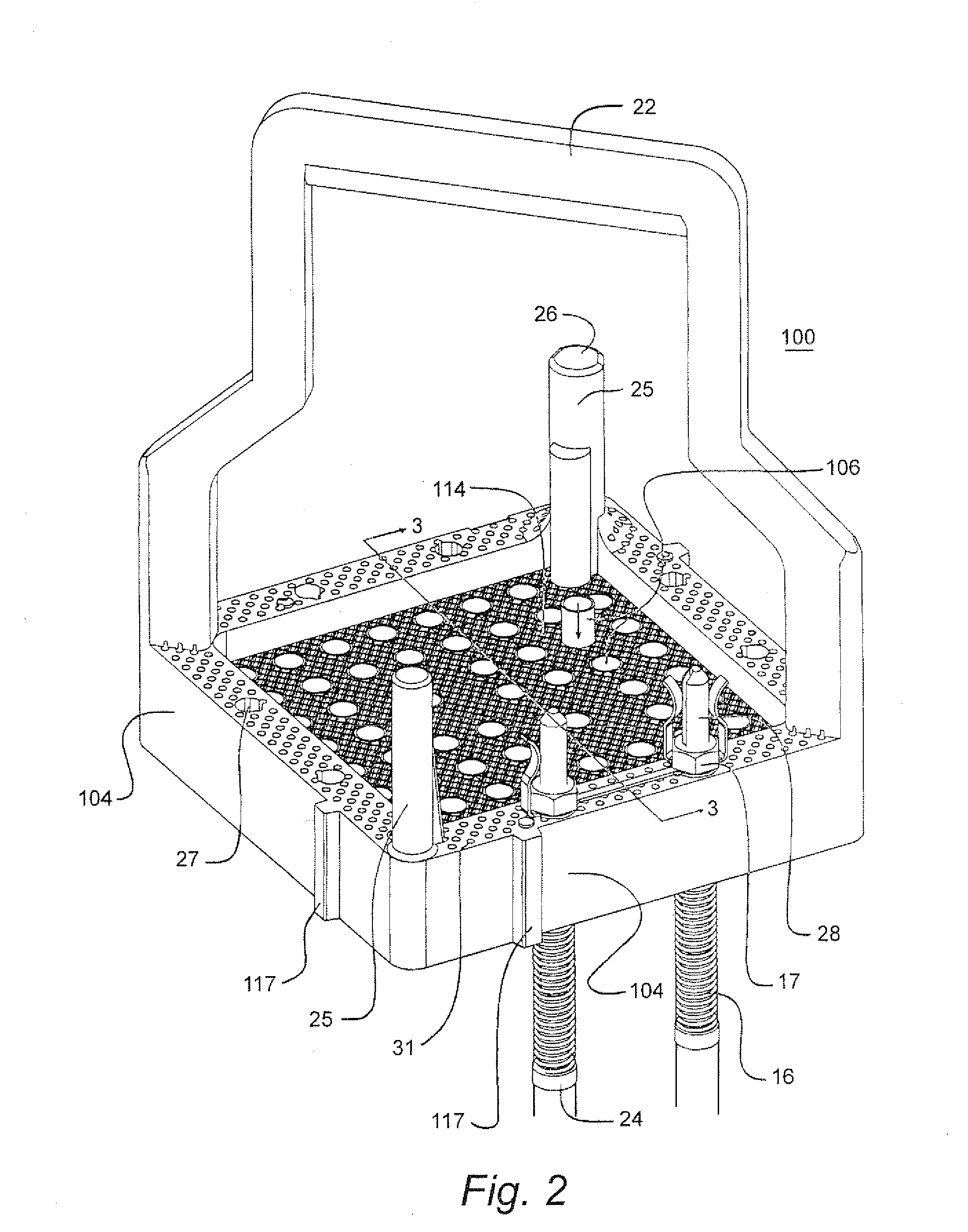
[0047]Each of the three embodiments of the debris shield 102, 136 and 152 are suitable for blocking and filtering debris from coolant flow passing through the upper tie plate. The debris shield 102 (first embodiment) may be held in place by, for example, one or more of the following methods: (i) threaded upper end plugs of the tie rods, (ii) the water rods 23, 230, (iii) the full length fuel rods 11 within the bundle assembly, and (iv) a binding force exerted between the cavity opening in the upper tie plate for the debris shield and the debris shield itself. Further, the debris shield 102 may be a removable unit or a permanent integrated structure mounted within the upper tie plate. In addition, the debris shield 102 may be a removable unit or a permanent integrated structure in the upper tie plate and above the fuel rods, wherein the debris shield has a surface at least co-extensive with an open area of the fuel bundle inside the channel.

[0048]The debris shields 102, 136 and 152 m...


PUM


Abstract

A nuclear reactor fuel assembly including: an upper tie plate having apertures to receive and support fuel rods of a fuel bundle; the fuel bundle includes an array of the fuel rods mounted and housed in the walls of a channel, and a load bearing or non-load bearing debris shield may be mounted in the upper tie plate, wherein the debris shield is porous to prevent the passage of debris. The debris shield is mounted in the frame of the upper tie plate. The debris shield can be either a removable unit, or it can be attached as a permanent integrated structure within the upper tie plate. The upper tie plate frame is also porous, e.g., has small vertical openings to allow fluid to pass through the frame and block passage of debris. The openings in the frame increase the effective flow area of passages through the upper tie plate and thereby compensate or offset any flow restrictions due to the debris shield. Preventing debris falling into the fuel bundle is expected to assure the operational life of the fuel assembly by reducing the risk of fuel rod failure and premature discharge from the reactor core.

Description

BACKGROUND OF THE INVENTION[0001]The present invention relates to a nuclear fuel assembly including a fuel bundle and a tie plate for supporting the fuel assembly and, particularly, relates to a debris shield that is releasably attached to or permanently integrated with an Upper Tie Plate (UTP) of the fuel assembly.[0002]In a nuclear fuel assembly, liquid coolant / moderator flows into the assembly thru the bottom and exits as a water and steam mixture from the top. The core of a boiling water nuclear reactor (BWR) includes a plurality of fuel assemblies arranged in vertical side-by-side relation, each containing a bundle of fuel rods. The fuel assemblies include a fuel bundle and a housing formed by a hollow metal channel. The fuel bundle includes an array of parallel fuel rods, water rods and one or more tie plates, spacers, and finger springs, that support the rods in the bundle. Generally, a fuel bundle includes an upper tie plate near the top of the bundle and a lower tie plate a...

Claims


Application Information

Patent Timeline
IPC IPC(8): G21C19/42
CPCG21C3/3206Y02E30/40G21C3/344G21C3/33Y02E30/30
Inventor DEFILIPPIS, MICHAELLUCIANO, GERALD A.SMITH, DAVIDKIERNAN, MICHAELCLARK, CARLTONLANGSTON, ANDREW K.
Owner GLOBAL NUCLEAR FUEL -- AMERICAS
Why Eureka
Try Eureka