Electrical connector with a pair of improved detacting pins

Inactive Publication Date: 2009-03-05
HON HAI PRECISION IND CO LTD
View PDF21 Cites 22 Cited by
  • Summary
  • Abstract
  • Description
  • Claims
  • Application Information

AI Technical Summary

Benefits of technology

[0007]An object of the present invention is to provide an e

Problems solved by technology

However, electrical reliability of the terminals will face challenge

Method used


Image

  • Electrical connector with a pair of improved detacting pins
  • Electrical connector with a pair of improved detacting pins
  • Electrical connector with a pair of improved detacting pins

Examples


Example

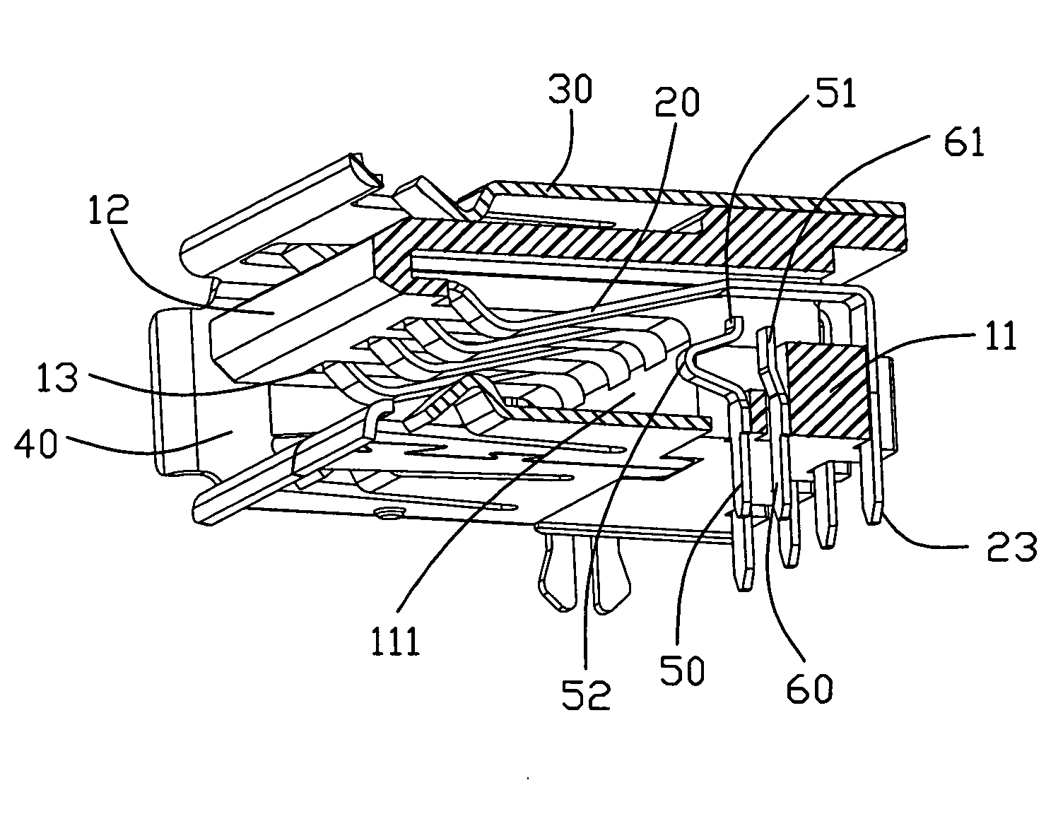
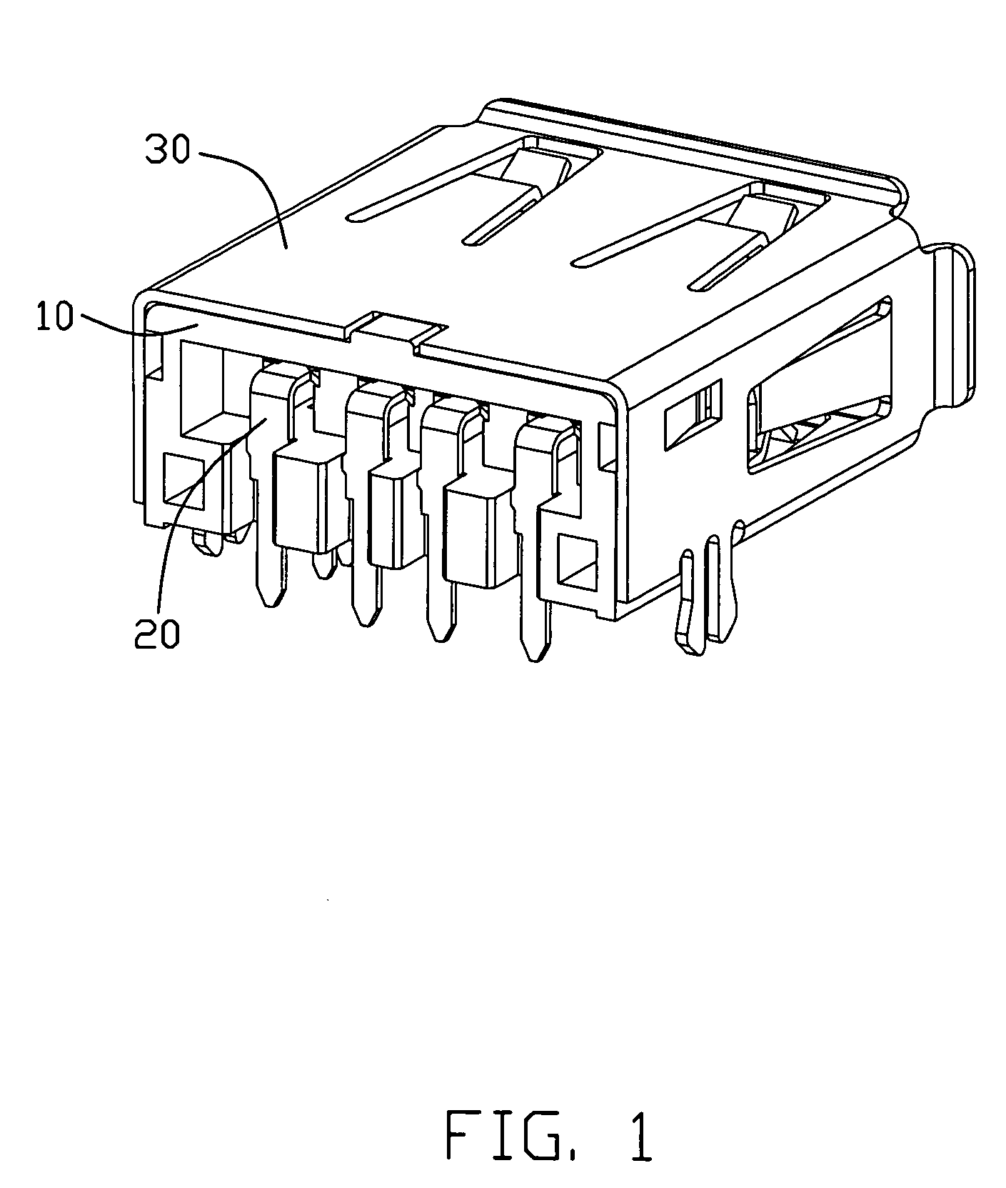
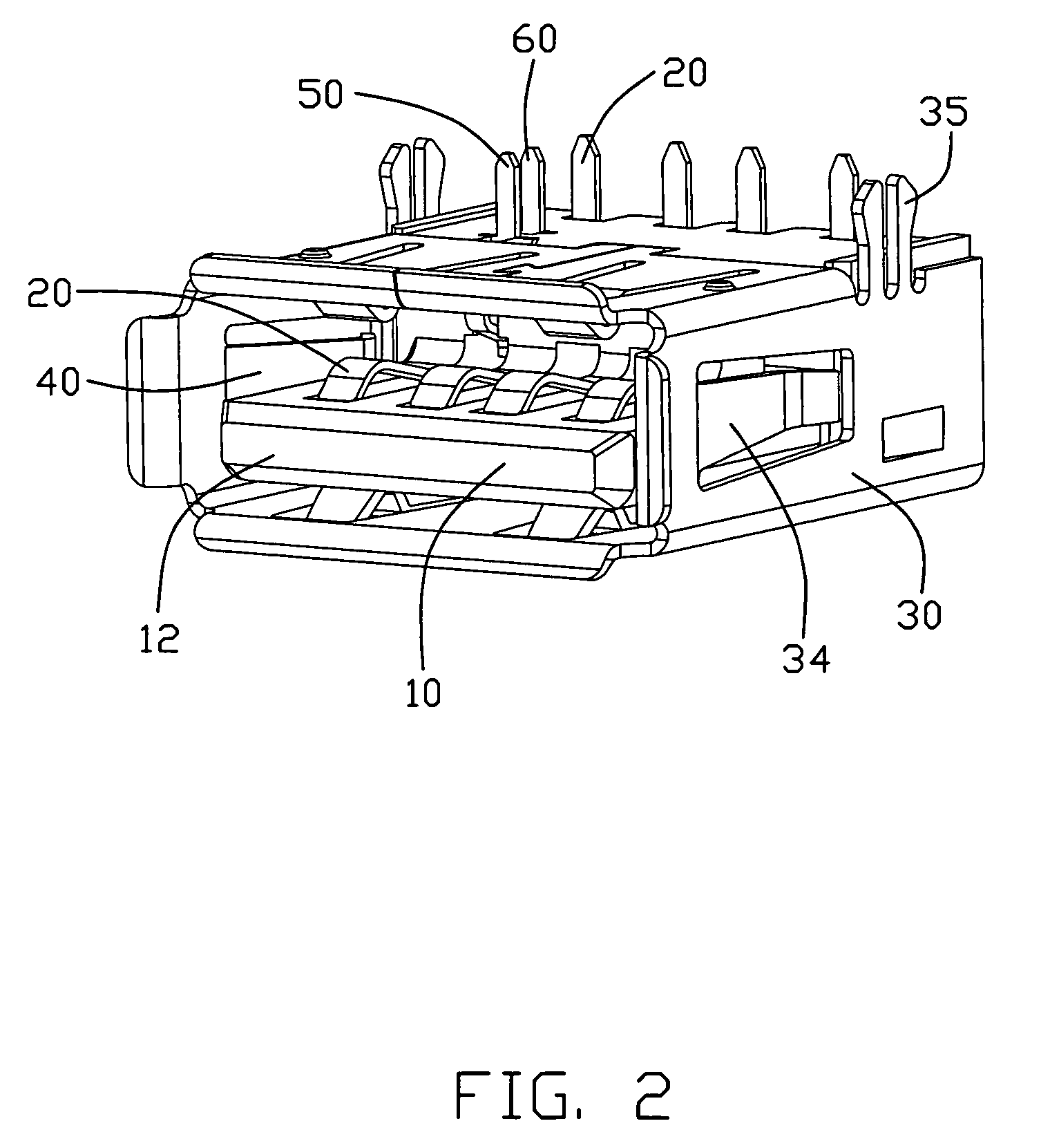
[0018]Referring to FIGS. 1 and 2, an electrical connector 1 of a first embodiment of the present invention is used to mate with a counter connector and comprises an insulating housing 10, a plurality of terminals 20 and a shielding shell 30.

[0019]Referring to FIGS. 4 and 5, the insulating housing 10 made from resin material comprises a base portion 11 and a tongue portion 12 extending forward from a front face 111 of the base portion. The bottom surface 115 of the tongue portion 12 defines four parallel passageways 13 which extend backward through the rear surface 112 of the base portion 11. A bottom surface 113, which functions as a connecting face to the PCB, has two holes 141, 142 arranged along a mating direction of the connector and the two holes communicate with the passageway 13. The front hole 141 communicates with the front face 111 of the base portion. The terminals are received in the passageways 13 and each terminal comprises a retaining section 22, a contacting section ...


PUM


Abstract

An electrical connector includes an insulating housing defining a base portion and a tongue portion extending forwards from a front face of the base portion, a plurality of terminals and a pair of detecting pins having a moveable pin and an immoveable pin. Each terminal defines a contacting portion located on the bottom face of the tongue portion and a solder leg extending towards a bottom face of the base portion. The two pins respectively define a contacting section spaced from and mating with each other and a leg section spaced from each other. The moveable pin defines an arc section projecting forwards beyond the front face of the tongue portion.

Description

BACKGROUND OF THE INVENTION[0001]1. Field of the invention[0002]The present invention relates to an electrical connector having a pair of detecting pins.[0003]2. Description of Related Art[0004]U.S. Pat. No. 5,674,085 discloses an electrical connector having a insulating housing defining a tongue portion, a shielding shell surrounding the housing and conductive terminals located on the tongue portion and a detecting pin. The detecting pin is retained in the housing and has a cantilever portion bent and extending below the tongue portion. The cantilever portion will engage with one conductive terminal when a mating connector is inserted into the connector to complete a detecting function.[0005]However, electrical reliability of the terminals will face challenge since one of the terminal functions as a detecting pin synchronously. The cantilever is longer so that it might be permanently distorted.[0006]Therefore, an electrical connector with improved detecting pins is desired to overc...

Claims


Application Information

Patent Timeline
IPC IPC(8): H01R29/00
CPCH01R13/65802H01R12/712H01R12/7023H01R13/7035H01R13/6582
Inventor QIN, FA-XIANGWANG, ZHEN-SHENG
Owner HON HAI PRECISION IND CO LTD
Why Eureka
Try Eureka