Data synchronizing signal detector, signal processing device using the detector, information recording and reproducing apparatus having the detector and the device, data synchronizing signal detecting method, and information recording medium for using in the method

Inactive Publication Date: 2001-11-22
HITACHI GLOBAL STORAGE TECH JAPAN LTD +1
View PDF1 Cites 12 Cited by
  • Summary
  • Abstract
  • Description
  • Claims
  • Application Information

AI Technical Summary

Benefits of technology

0015] According to a first aspect of the invention, there is provided an information recording and reproducing apparatus comprising a data discriminator including data discrimination means and sync signal discrimination means, wherein the detection of the data sync signal is carried out for a discriminated bit string output from the sync signal discrimination means while at the same time carrying out the data demodulation for a discriminated bit string output from the data discrimination means. As a result, the discrimination of the data sync signal and the data reproduction and

Problems solved by technology

Even in the case where the data decoded in the data section 78 has a very good error rate, a detection error (i.e. failure to detect at the right position or detection at a wrong position) of the data sync signal 77 which is normally about several bytes will lead to the failure to correctly decode the subsequent data section 78 which lasts several tens of bytes to several hundred bytes, thereby extremely deteriorating the whole error rate.
Thus, the bit interval is required to be reduced as compa

Method used


Image

  • Data synchronizing signal detector, signal processing device using the detector, information recording and reproducing apparatus having the detector and the device, data synchronizing signal detecting method, and information recording medium for using in the method
  • Data synchronizing signal detector, signal processing device using the detector, information recording and reproducing apparatus having the detector and the device, data synchronizing signal detecting method, and information recording medium for using in the method
  • Data synchronizing signal detector, signal processing device using the detector, information recording and reproducing apparatus having the detector and the device, data synchronizing signal detecting method, and information recording medium for using in the method

Examples


first embodiment

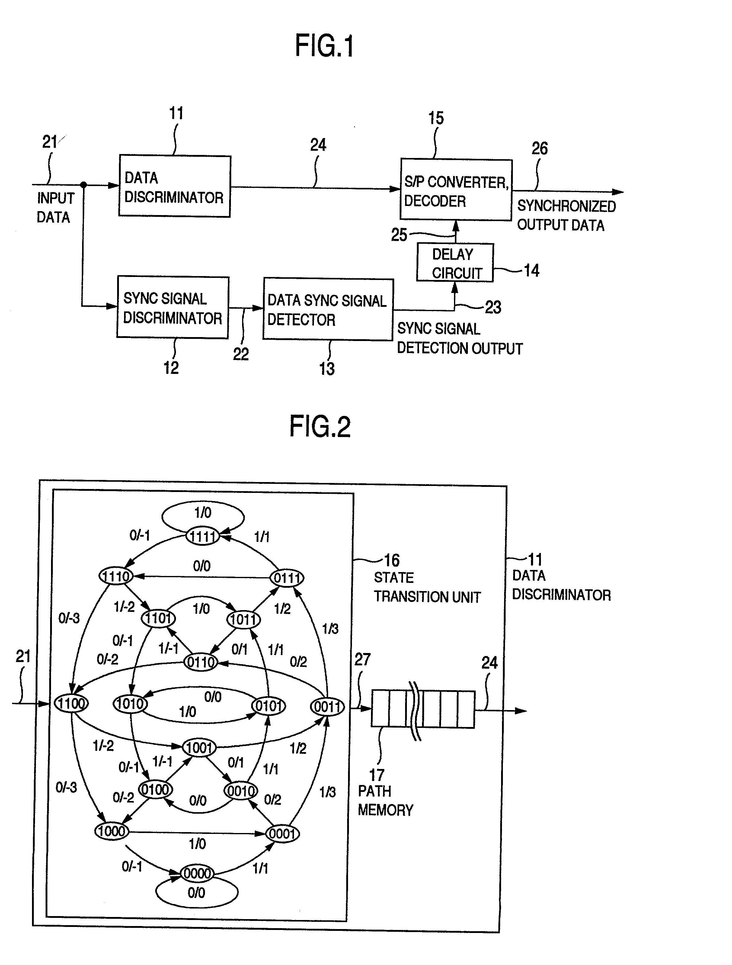
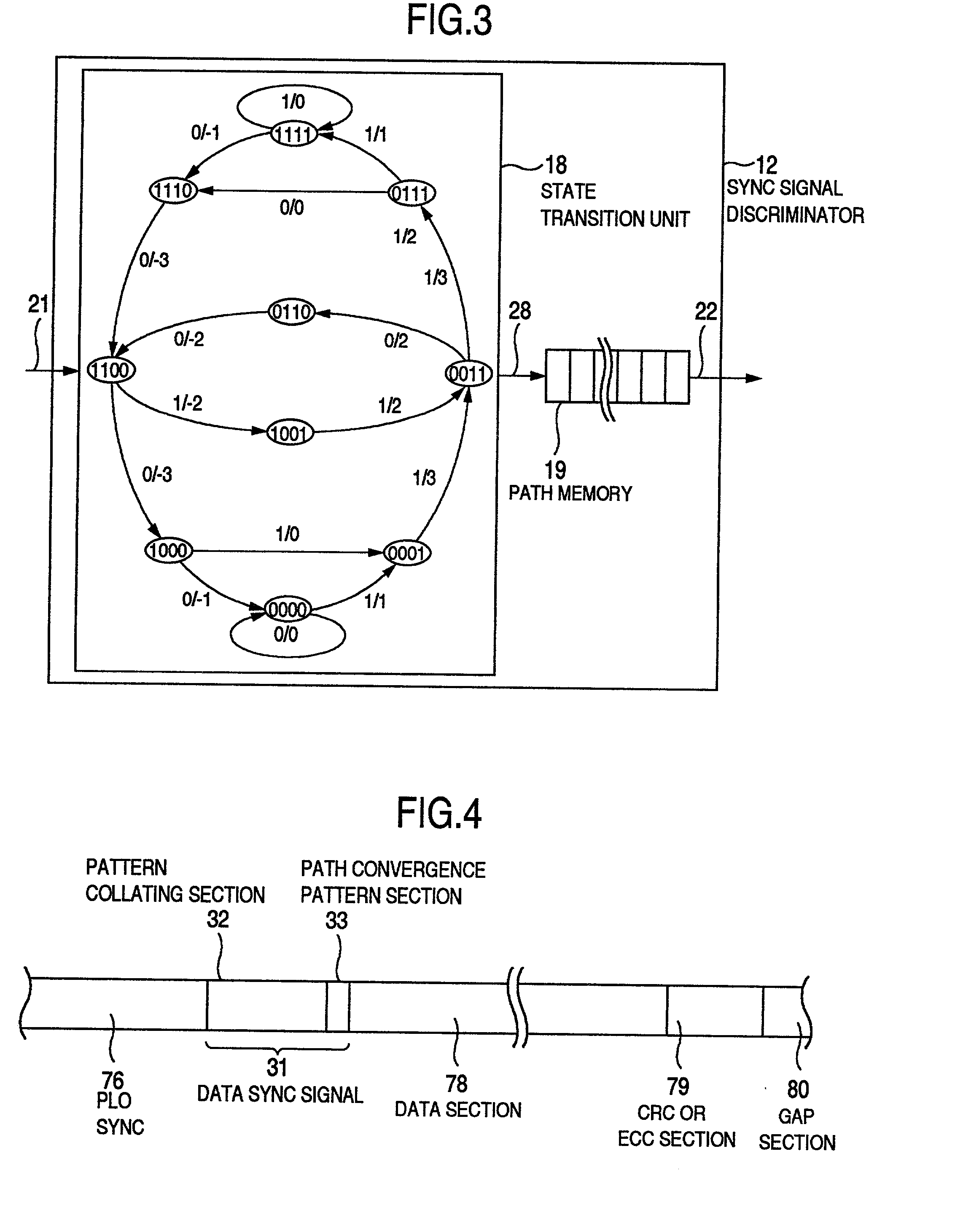
[0051] A data sync signal detector according to the invention will be explained with reference to FIGS. 1 to 5. First, in the data sync signal detector shown in FIG. 1, input data 21 are input to a data discriminator 11 and a sync signal discriminator 12. The data discriminator 11 discriminates the data in the input data 21 and produces a data discrimination output 24 as a discriminated code bit output. The sync signal discriminator 12 processes the input data 21 for data discrimination and produces a sync signal discrimination output 22 as a discriminated code bit output. A data sync signal detector 13 is supplied with the sync signal discrimination output 22, detects the data sync signal in the input data 21 and produces a sync signal detection output 23. The conventional method can be applied directly to the detection of the data sync signal in the data sync signal detector 13.

[0052] A delay circuit 14 delays the sync signal detection output 23 by a predetermined length of time a...

second embodiment

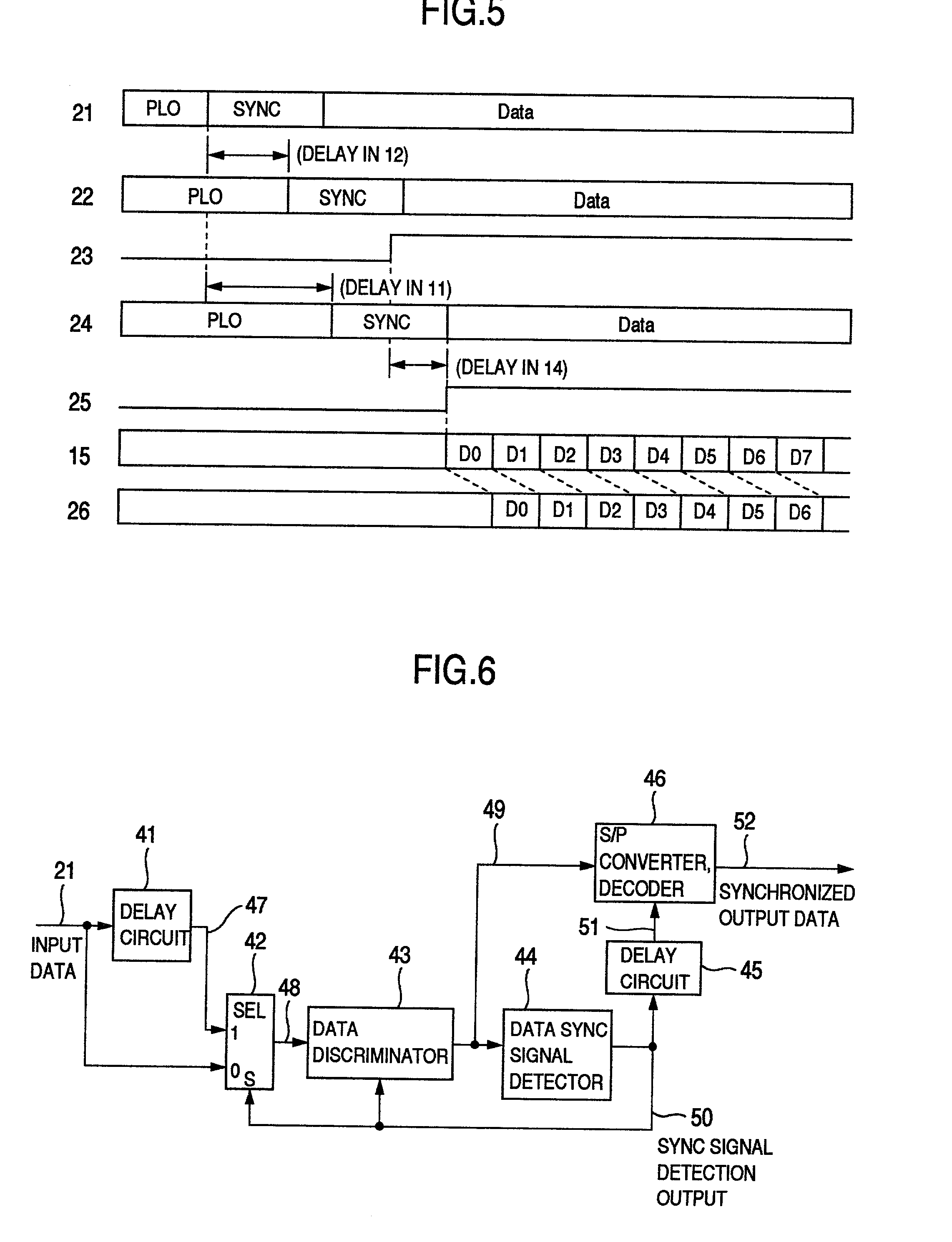
[0084] Now, the invention will be explained with reference to FIGS. 6 to 8. According to this embodiment, as shown in FIG. 6, the input data 21 is applied to a delay circuit 41 and a signal selector 42. The input data delay output 47 produced as the input data 21 delayed in the delay circuit 41 is applied to the other input terminal of the signal selector 42. The signal selector 42 selects the signal of the input data 21 or the input data delay output 47, and produces the selected signal as an input data select output 48. The input data select output 48 is applied to a data discriminator 43.

[0085] The data discriminator 43 produces a data discrimination output 49 as the result of discrimination. The data discrimination output 49 is applied to a data sync signal detector 44 and a serial-to-parallel converter or a decoder 46. The data sync signal detector 44 detects the data sync signal in the input data 21 and produces a sync signal detection output 50. The conventional method is dir...

third embodiment

[0101] Now, the invention will be explained with reference to FIGS. 9 to 11. First, referring to FIG. 9, the input data 21 is applied to the delay circuit 81 and the signal selector 82 according to this embodiment. The input data delay output 87 constituted of the input data 21 delayed by the delay circuit 81 is input from the other input terminal of the signal selector 82. The signal selector 82 selects the signal of the input data 21 or the signal of the input data delay output 87, and produces the selected signal as an input data select output 88. The input data select output 88 is applied to the data discriminator 83.

[0102] The data discriminator 83 discriminates the input data select output 88 and produces the sync signal discrimination output 89 and the data discrimination output 92. The sync signal discrimination output 89 is applied to the data sync signal detector 84. The data discrimination output 92 is applied to the serial-to-parallel converter or the decoder 86. The dat...


PUM


Abstract

A data discriminating unit includes a data discriminator and a sync signal discriminator. A data sync signal is detected for the bit string discriminated from the output of the sync signal discriminator, and the data is demodulated for the bit string discriminated from the output of the data discriminator, thereby optimizing the signal to a form suitable for discrimination and detection of the data sync signal and demodulation for data reproduction. As a result, the detection performance of the data sync signal can be improved while maintaining the data discrimination performance. A Viterbi decoder is used for discrimination by the data discriminator and the sync signal discriminator for the optimization thereby to optimize the number of states, the number of paths for state transition and the path memory length. A signal having no continuous inversions of the recording data is used as the data sync signal.

Description

[0001] 1. Field of the Invention[0002] The present invention relates to an information recording and reproducing apparatus, or in particular to a technique for improving the detection rate of a data synchronizing (hereinafter referred to as "sync") signal by improving the performance of data discrimination of a data sync signal section.[0003] 2. Description of the Related Art[0004] FIG. 27 shows an example of the recording format in a magnetic disk device. Data are recorded or reproduced in and from each sector of a recording medium constituting a unit storage area. Each sector includes a PLO (phase locked oscillator) sync area 76 for pull-in of a PLL (phase locked loop), a data sync signal 77 for producing a decode timing signal for a modulated code by detecting the start position of the data, a data section 78 for actually recording and reproducing the data, and a CRC (cyclic redundancy check) or an ECC (error correcting code) 79 for detecting or correcting errors. A gap 80 consti...

Claims


Application Information

Patent Timeline
IPC IPC(8): G11B20/14G11B5/012G11B5/09G11B20/10G11B20/18G11B27/10G11B27/30H04L1/00H04L7/04H04L7/08
CPCG11B5/012G11B5/09G11B20/10009G11B27/10G11B27/3027H04L1/0041H04L1/0047H04L1/0054H04L7/0008H04L7/04
Inventor WATANABE, YOSHIJUTAKASHI, TERUMI
Owner HITACHI GLOBAL STORAGE TECH JAPAN LTD
Why Eureka
Try Eureka