Micromechanical filter for microparticles, in particular for pathogenic bacteria and viruses, and also process for production thereof

Inactive Publication Date: 2011-05-12
FRIEDBERGER ALOIS +1
View PDF10 Cites 12 Cited by
  • Summary
  • Abstract
  • Description
  • Claims
  • Application Information

AI Technical Summary

Benefits of technology

[0009]The present invention provides for a filter for microparticles and, in particular, for bacteria and viruses, which effectively

Problems solved by technology

Above all, conventional filters embodied as volume filters have the disadvantage of rapid so

Method used


Image

  • Micromechanical filter for microparticles, in particular for pathogenic bacteria and viruses, and also process for production thereof
  • Micromechanical filter for microparticles, in particular for pathogenic bacteria and viruses, and also process for production thereof
  • Micromechanical filter for microparticles, in particular for pathogenic bacteria and viruses, and also process for production thereof

Examples


first embodiment

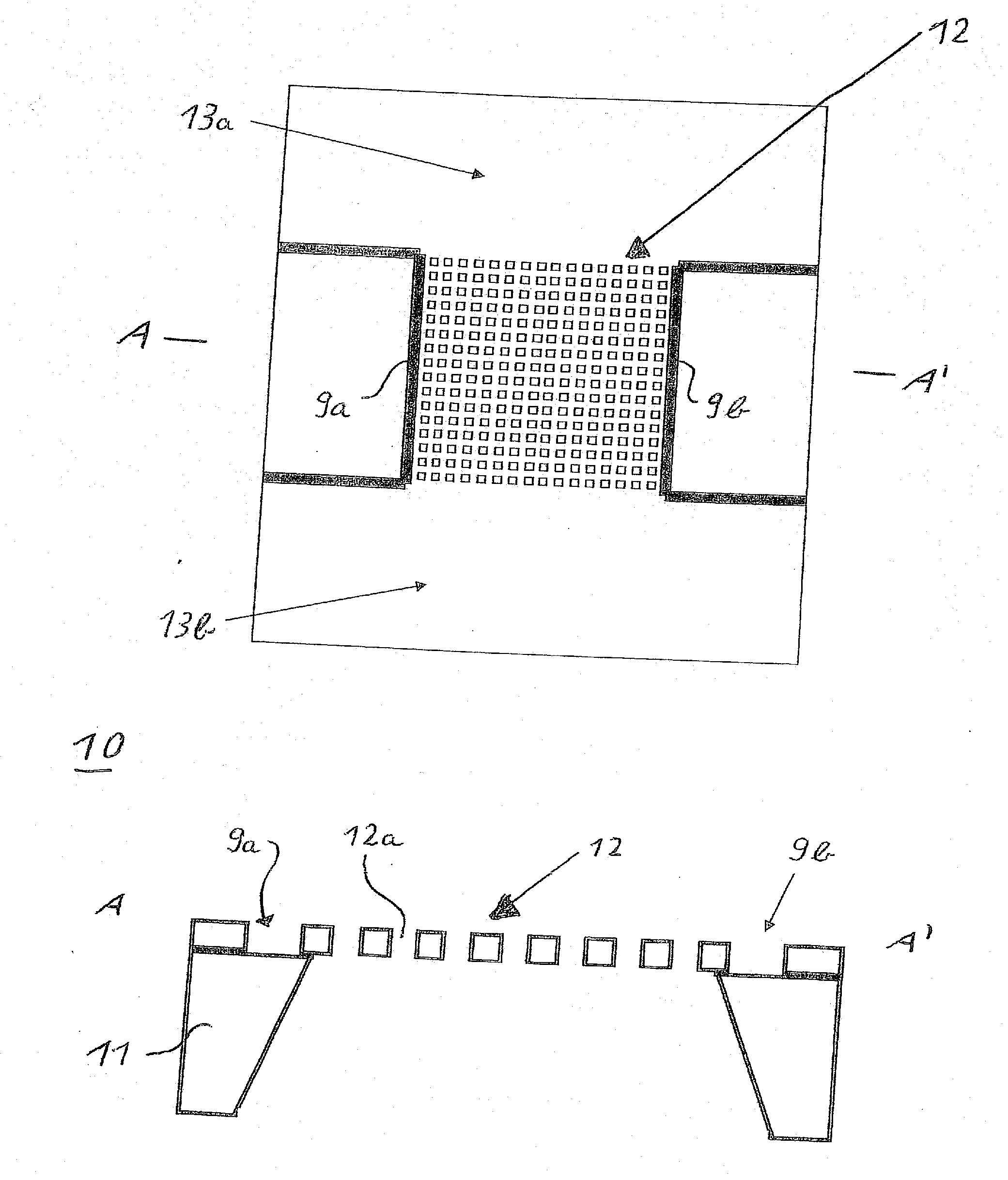
[0042]FIG. 1 shows a micromechanical filter 10 as the invention in a plan view and as a sectional view along the line A-A′. The micromechanical filter 10 has in its lower area a structured substrate 11 that bears a perforated membrane 12. The membrane 12 is provided with through holes 12a and serves to filter out microparticles from a medium while flowing through the membrane 12. A first contact surface 13a and a second contact surface 13b for the electrical connection of a power supply are located on the top of the membrane 12. The power supply provides an electric current between the contact surfaces 13a and 13b through the perforated membrane 12 so that this is heated based on the current flow. At a heating temperature of, e.g., 700° C. to 1,000° C., a combustion occurs of the filtered-out microparticles that are located on the surface of the membrane 12. That means that the two contact surfaces 13a, 13b form a device for removing the filtered-out microparticles from the surface ...

third embodiment

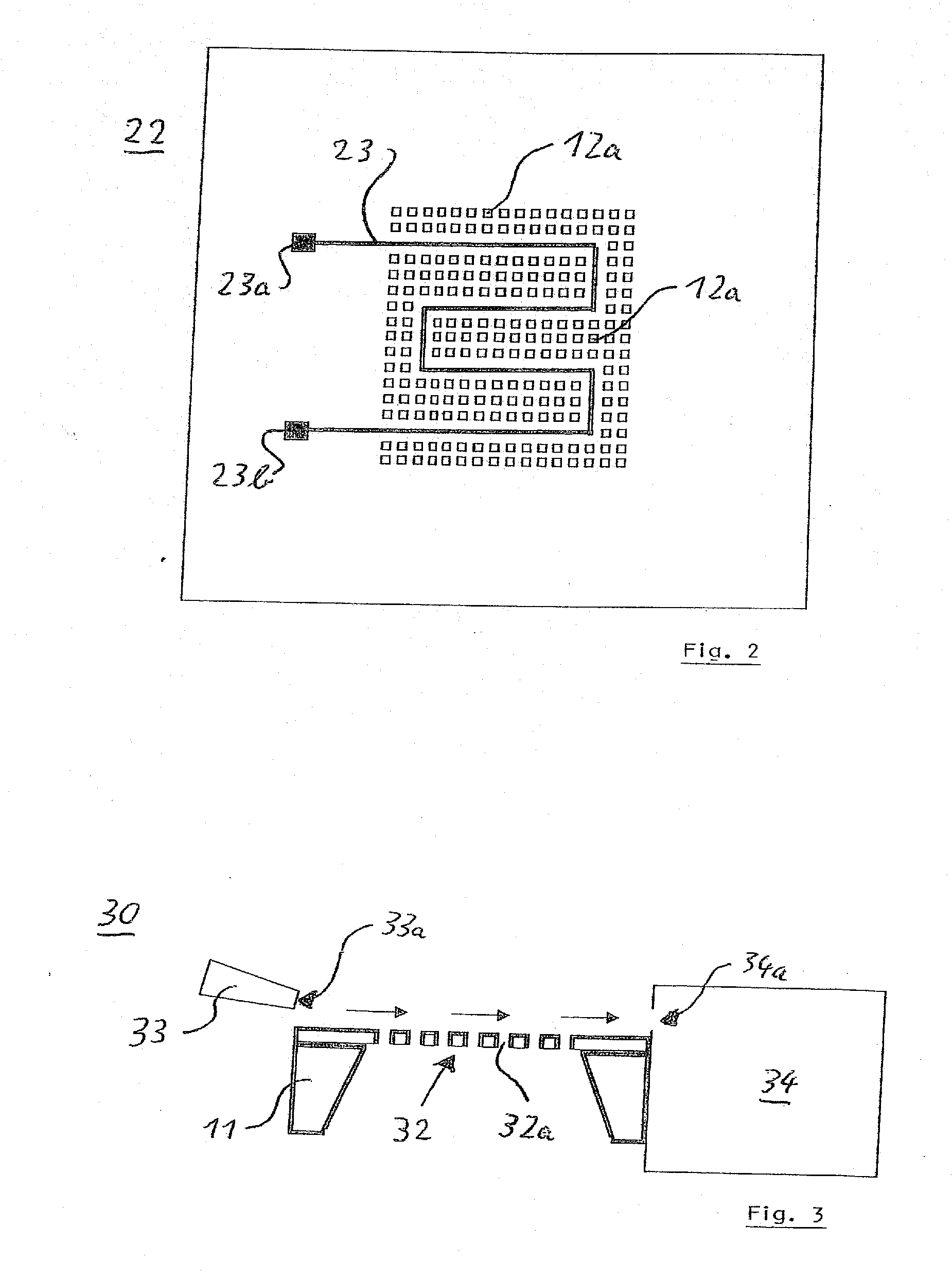
[0049]FIG. 3 shows a micromechanical filter 30 according to the invention. The micromechanical filter 30 has a structured substrate 11 embodied as a carrier, on which substrate a perforated membrane 32 is supported which is provided with through holes 32a. The membrane 32 is permanently connected to the substrate 11 lying beneath. At the side of the membrane 32 a microinjector 33 is provided, which generates a liquid flow or a gas flow along the surface of the membrane 32 or parallel thereto, in order to remove microparticles located there which are deposited as residues on the membrane 32 after the filter process. To this end, an opening 33a of the microinjector 33 is embodied as a nozzle that is directed onto the surface of the membrane 32 in the area of the through holes 32a. The microinjector 33 comprises a micropump, in order to pump a liquid or gaseous medium for rinsing the membrane surface through the nozzle-shaped opening 33a.

[0050]A microreactor 34 with a detection device...

fourth embodiment

[0052]FIG. 4 shows a membrane 42 of a filter according to the invention. An actuator structure 43 for exciting surface waves in the area of the perforated membrane 42 is thereby arranged on the membrane 42. The substrate lying beneath is embodied as in the other embodiments already discussed.

[0053]The actuator structure 43 comprises, for example, one or more FPW structures (flexural plate wave) that are arranged on a chip surface or membrane surface in order to generate an agitation on the surface thereof. This agitation serves to accelerate biochemical processes on the membrane surface and / or the transportation away from the filter surface of the microparticles or germs that are deposited as residues on the filter surface.

[0054]A method for producing the micromechanical filter is described below based on FIGS. 5a and 5b.

[0055]First a prepared substrate 7, which is made, e.g., of silicon, is porosified starting from the surface thereof, so that it is pervaded by thin channels or ho...


PUM

PropertyMeasurementUnit
Flow rateaaaaaaaaaa
Currentaaaaaaaaaa
Depthaaaaaaaaaa

Abstract

A micromechanical filter for microparticles is suitable in particular for filtering pathogenic bacteria and viruses, and comprises a substrate and a perforated membrane permanently connected to the substrate, for filtering out microparticles from a medium while flowing through the membrane, and furthermore a device for removing the filtered-out microparticles from the surface of the membrane. The device for removing the microparticles is embodied, for example, as a heating device, in order to burn the microparticles located on the surface of the membrane. It can also be embodied as an actuator structure for deforming the membrane or as a microinjector for generating a flow parallel to the surface of the membrane.

Description

BACKGROUND OF THE INVENTION[0001]1. Field of the Invention[0002]The invention relates to a micromechanical filter for microparticles, in particular for pathogenic bacteria and viruses, with a substrate and a perforated membrane permanently connected to the substrate, for filtering out microparticles from a medium while flowing through the membrane, as well as a method for producing a micromechanical filter.[0003]2. Background Information[0004]Micromechanical filters for microparticles, such as, for example, pathogenic bacteria, other germs, viruses, etc., can be used in particular in the area of drinking water supply in order to protect drinking water networks from contamination. The supply networks must thereby be protected on the one hand from penetration by undesirable particles, on the other hand it is necessary to detect existing particles and if necessary to determine their degree of contamination or a number of germs or bacteria or also viruses. Pathogens, such as for example...

Claims


Application Information

Patent Timeline
IPC IPC(8): B01D71/02B01D65/02B01D69/12B01D67/00
CPCB01D61/18B01D65/02B01D65/022B01D65/08B01D67/0032Y10T29/49B01D71/02B01D2321/00B01D2321/2033C12Q1/06B01D2325/24B01D67/0034
Inventor FRIEDBERGER, ALOISMUELLER, GERHARD
Owner FRIEDBERGER ALOIS
Why Eureka
Try Eureka