Method of Determining the Presence of a Mineral Within a Material

Inactive Publication Date: 2009-12-24
THE UNIV OF QUEENSLAND
View PDF3 Cites 8 Cited by
  • Summary
  • Abstract
  • Description
  • Claims
  • Application Information

AI Technical Summary

Benefits of technology

[0067]If a thermal imager is employed, this may be an infra-red imager. Furthermore, the apparatus may include additional thermal imagers. In one embodiment, the apparatus further include a cool region, the cool region being of relatively lower temperature to the rest of the apparatus. The thermal imager/s may then be positioned about the cool region providing for improved detection of radiation emitted from the material as it passes through the microwave irradiation zone.
[0068]Considering that the speed of the material through the microwave irradiation zone could be up to several metres per second, it is important that the material residence time within microwave irradiation zone is sufficiently long to induce the required amount of heating of the minerals of interest to allow for their efficient identification. Preferably, the microwave absorbing minerals will be heated to a temperature which is significantly higher (10-50° C.) from the temperature of the microwave non-absorbing mineral

Problems solved by technology

However, when constant microwave radiation is used rock fragments tend to heat very quickly throughout, reducing the detectable difference between the different components within the rock sample and forming the surface of the rock sample.
However, the efficacy of the sorting method is not high as it does not allow for the assessment of the level of microwave heating-associated mineral within the rock.
Furthermore such m

Method used


Image

  • Method of Determining the Presence of a Mineral Within a Material
  • Method of Determining the Presence of a Mineral Within a Material
  • Method of Determining the Presence of a Mineral Within a Material

Examples


Embodiment Construction

[0077]It will be convenient to hereinafter provide a detailed description of certain embodiments of the invention with reference to the accompanying drawings. The purpose of providing this detailed description is to instruct persons having an interest in the subject matter of the invention how to put the invention into practice. It is to be clearly understood however that the specific nature of this detailed description does not supersede the generality of the preceding statements.

[0078]In the drawings:

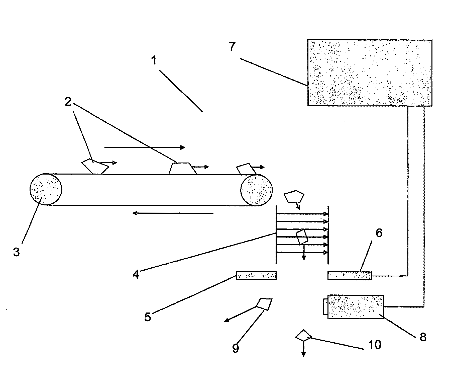
[0079]FIG. 1 illustrates an apparatus according to one embodiment of the invention;

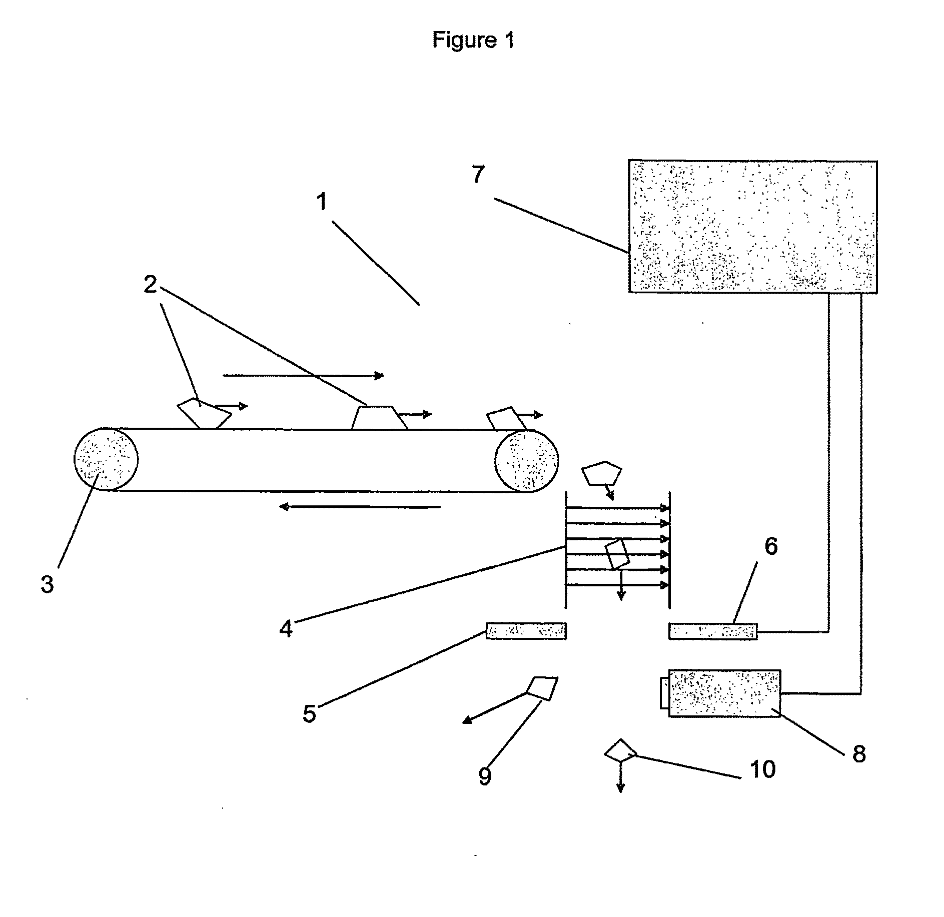
[0080]FIG. 2 is an IR image of a high grade copper ore, medium grade copper ore and a barren rock after brief exposure to microwave heating;

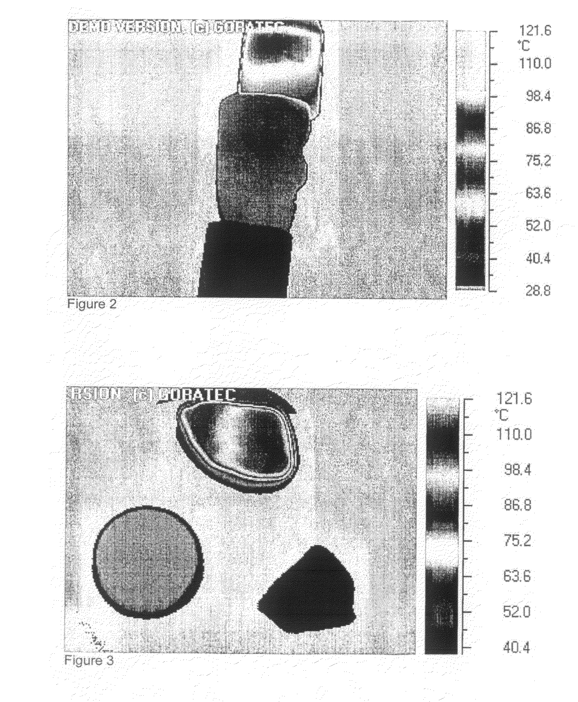
[0081]FIG. 3 is an IR image of a high grade ore fragment, a sandstone fragment and waste rock after brief exposure to microwave heating;

[0082]FIG. 4 is an IR image of a high grade copper ore, homogenous sandstone, waste rock and low grade copper ore after brief expo...


PUM


Abstract

The invention relates generally to a method of determining the presence of a mineral within a material, such as a rock, a rock fragment, soil, sand or other geological material including: applying pulsed microwave radiation to the material; detecting radiation emitted from the material after the application of the pulsed microwave radiation; and analysing the detected radiation to determine the presence of mineral within the material. The invention also provides a method of sorting rock fragments into at least two streams using this method and an apparatus for carrying out the method.

Description

FIELD OF THE INVENTION[0001]The invention relates primarily to a method of determining the presence or absence of a mineral within a material, be that a rock fragment in the laboratory or a rock body in situ, for example. The invention also relates to a method of sorting rock fragments, such as ore fragments, based on a determination according to the above method. Still further, the invention relates to an apparatus for determining the presence of a mineral within a material.[0002]The invention has particular but not exclusive application to assessing mineral content and / or distribution within and on the surface of rock fragments, and for illustrative purposes particular reference will be made to this application. However, it is to be understood that this invention could be used in other applications, such as assessing mineral content and or distribution within rock bodies in situ, in soils or sands, in mining, in other geological contexts and in research.BACKGROUND TO THE INVENTION...

Claims


Application Information

Patent Timeline
IPC IPC(8): G01N22/00G01N9/24
CPCB07C5/344G01N33/24G01N22/00B07C5/366
Inventor DJORDJEVIC, NENAD
Owner THE UNIV OF QUEENSLAND
Why Eureka
Try Eureka