Rotation detection device and power steering device

Active Publication Date: 2016-01-21
HITACHI ASTEMO LTD
View PDF9 Cites 10 Cited by
  • Summary
  • Abstract
  • Description
  • Claims
  • Application Information

AI Technical Summary

Benefits of technology

[0007]Accordingly, in the invention, the deformation of the detecting me

Problems solved by technology

However, in the above-mentioned hitherto-used technology, due to cooling contracture induced by the insert molding, internal stress is inevitably produced in the detecting m

Method used


Image

  • Rotation detection device and power steering device
  • Rotation detection device and power steering device
  • Rotation detection device and power steering device

Examples


first embodiment

[0028]First, the construction will be described.

[0029][Electric Power Steering Device]

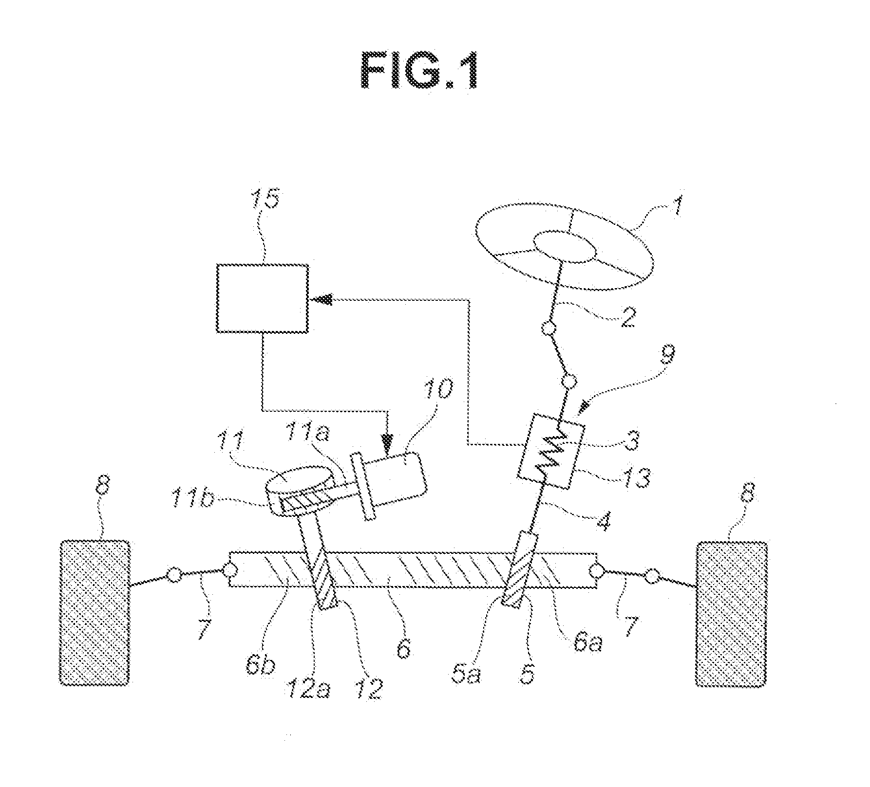
[0030]FIG. 1 is an entire constructional view of an electric power steering device of a first embodiment.

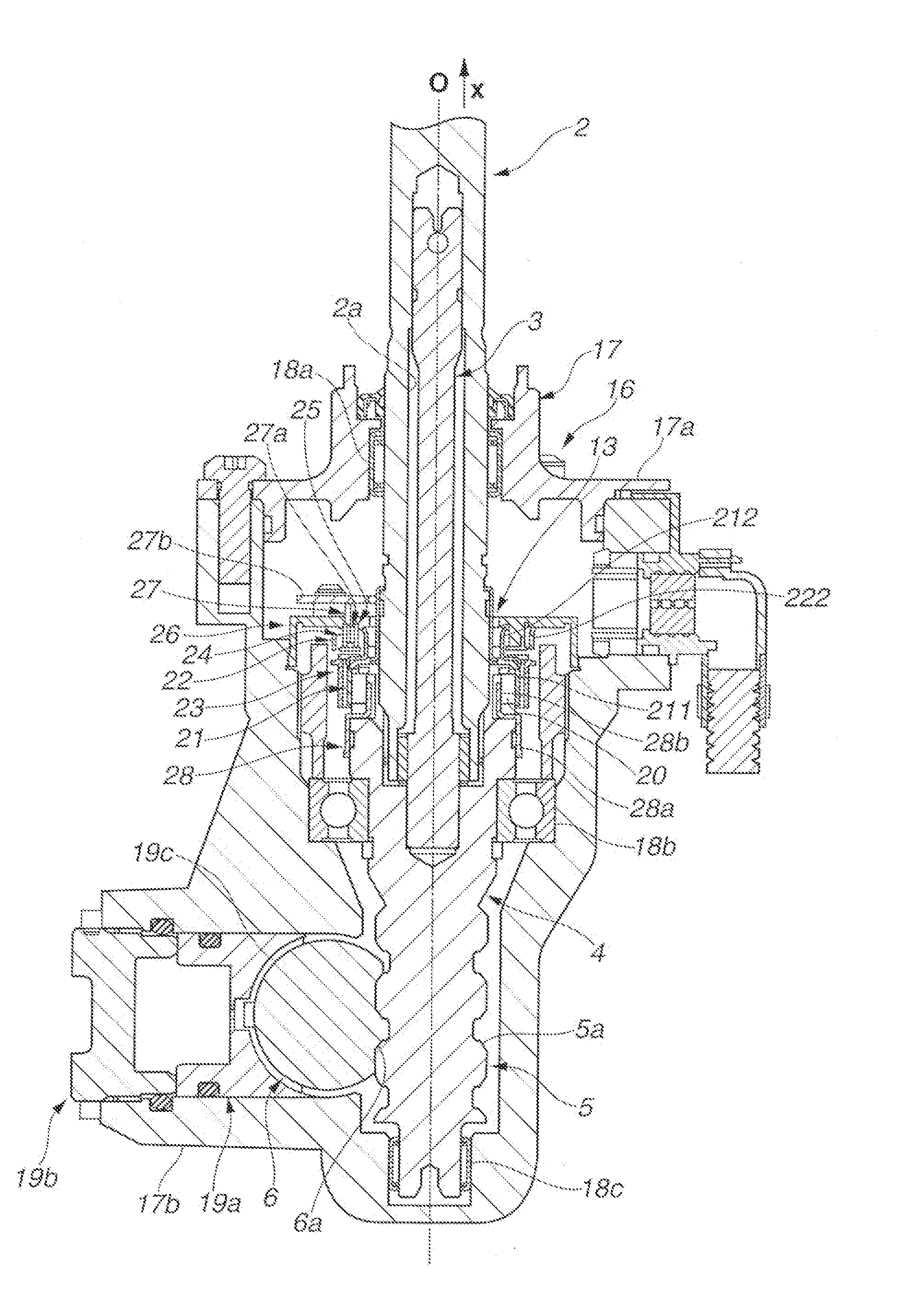
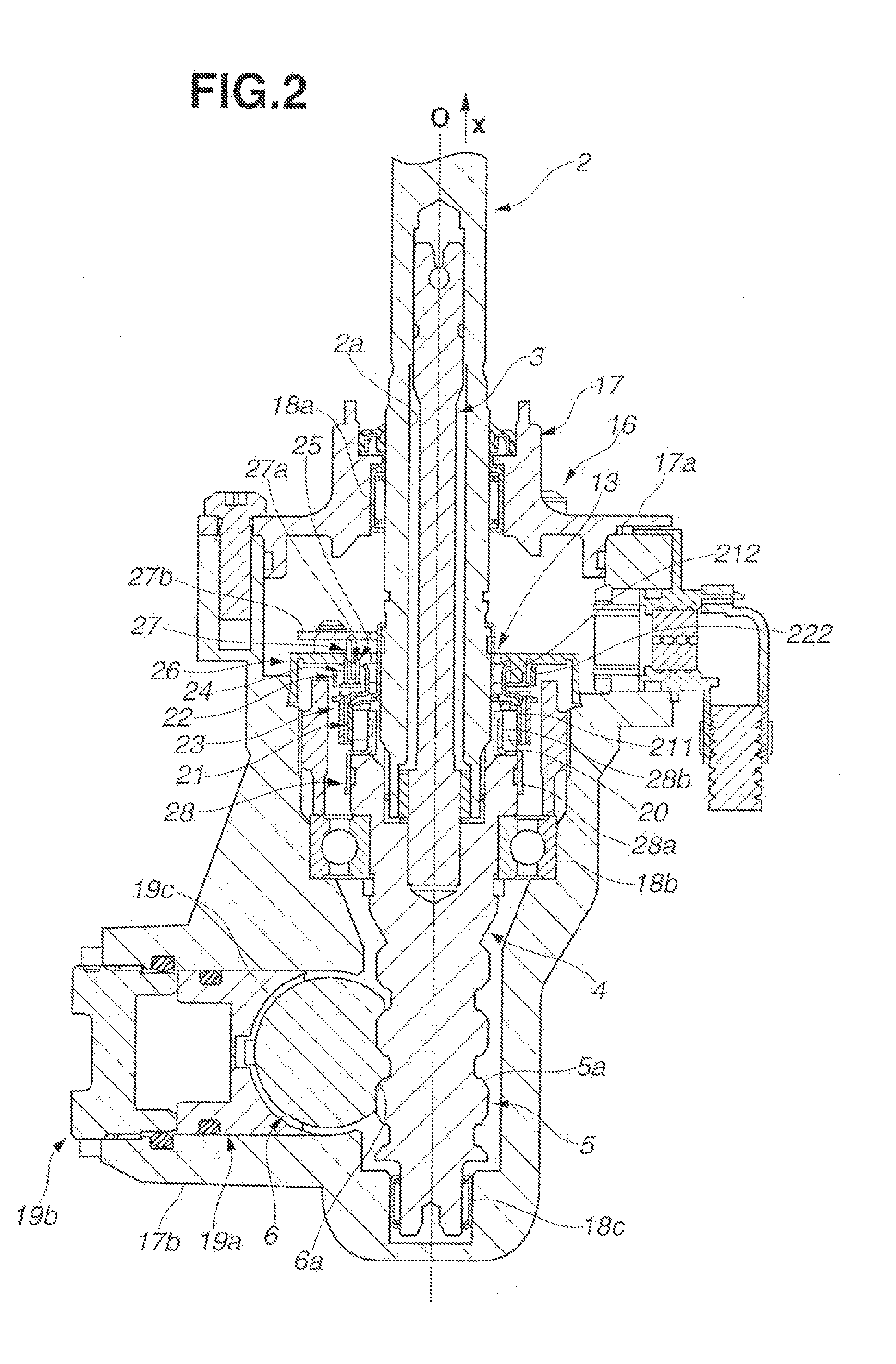
[0031]A steering force applied to a steering wheel 1 by a driver is transmitted as a rotary motion to a first pinion 5 through a steering shaft (second member, input shaft) 2, a torsion bar 3 and a pinion shaft (first member, output shaft) 4 and transformed into a linear motion by a rack bar 6 that has first rack teeth 6a meshed with pinion teeth 5a of the first pinion 5. The linear motion of the rack bar 6 is transmitted to steered road wheels 8 and 8 through tie-rods 7 and 7. The steering shaft 2, the torsion bar 3, the pinion shaft 4, the first pinion 5, the rack bar 6 and the tie-rods 7 and 7 constitute a steering mechanism 9 through which the steering operation of the steering wheel 1 is transmitted to the steered road wheels 8.

[0032]While, an output of an electric motor 10 is transmitted t...


PUM


Abstract

A welding plate 29 and a yoke holder 23 are welded and fixed to each other having a pair of yokes 21 and 22 put therebetween.

Description

TECHNICAL FIELD[0001]The present invention relates to a rotation detecting device and a power steering device.BACKGROUND ART[0002]A hitherto-used rotation detecting device comprises a permanent magnet and a pair of yokes that are rotatable relative to each other, a pair of magnetism collecting rings that induce magnetic fluxes produced between the paired yokes due to the relative rotation between the permanent magnet and the paired yokes, and a Hall IC sensor that detects the magnetic fluxes between the magnetism collecting rings. The paired yokes and the paired magnetism collecting rings that constitute a detecting member are constructed of a soft magnetic material such as Permalloy (permeability alloy) or the like and integrally molded with a resin holder through an insert molding technique, and the yokes and magnetism collecting rings are connected to input / output shafts or a housing through the holder. One example of the above-mentioned technology is described in Patent Document...

Claims


Application Information

Patent Timeline
IPC IPC(8): B62D6/10B62D5/04G01D5/14
CPCB62D6/10G01D5/142B62D5/0421B62D5/04G01L3/10G01L3/104G01L5/221
Inventor YOSHIDA, OSAMUMARUYAMA, TATSUYOSHISHIRAKUBO, KIYOTAKA
Owner HITACHI ASTEMO LTD
Why Eureka
Try Eureka