Vehicle Hood Assembly with Rippled Cushion Support

a cushion support and hood technology, applied in the direction of roofs, vehicular safety arrangments, pedestrian/occupant safety arrangements, etc., can solve the problems of limiting the ability of the hood to absorb energy through deformation, etc., to achieve improved and more uniform crush characteristics, improve crush performance, and improve the effect of kinetic energy absorption

Active Publication Date: 2009-03-12
GM GLOBAL TECH OPERATIONS LLC
View PDF50 Cites 22 Cited by
  • Summary
  • Abstract
  • Description
  • Claims
  • Application Information

AI Technical Summary

Benefits of technology

[0005]An energy-absorbing vehicle hood assembly having a rippled cushion support is provided, offering improved crush performance and more uniform kinetic energy absorption. The improved and more uniform crush characteristics of the present hood assembly ensure a compliant surface when subjected to a crush load upon impact with a foreign object. As such, the present design maximizes the hood assembly's ability to absorb and attenuate kinetic energy imparted thereto, and thereby minimize the required stopping distance of the object. In addition, the orientation, regional variation, and design of the rippled cushion support improves vehicle crashworthiness in frontal impact scenarios—reducing dash panel intrusion and effective vehicle acceleration. The hood assembly and rippled cushion support also provides a relatively high bending stiffness, enabling sufficient rigidity and stability when the vehicle is in normal operation, rendering the present hood assembly resistant to flutter or shake dynamics that may occur at high vehicle speeds, and sufficiently resilient to meet standard performance requirements.

Problems solved by technology

However, the deformability of the hood and, correspondingly, the hood's ability to absorb energy may be impeded by the proximity of the hood to rigidly mounted components housed in the vehicle's engine (or forward) compartment.
By way of example, the hood's ability to absorb energy through deformation can be significantly impeded where the hood and engine block are in close proximity.

Method used


Image

  • Vehicle Hood Assembly with Rippled Cushion Support
  • Vehicle Hood Assembly with Rippled Cushion Support
  • Vehicle Hood Assembly with Rippled Cushion Support

Examples


Embodiment Construction

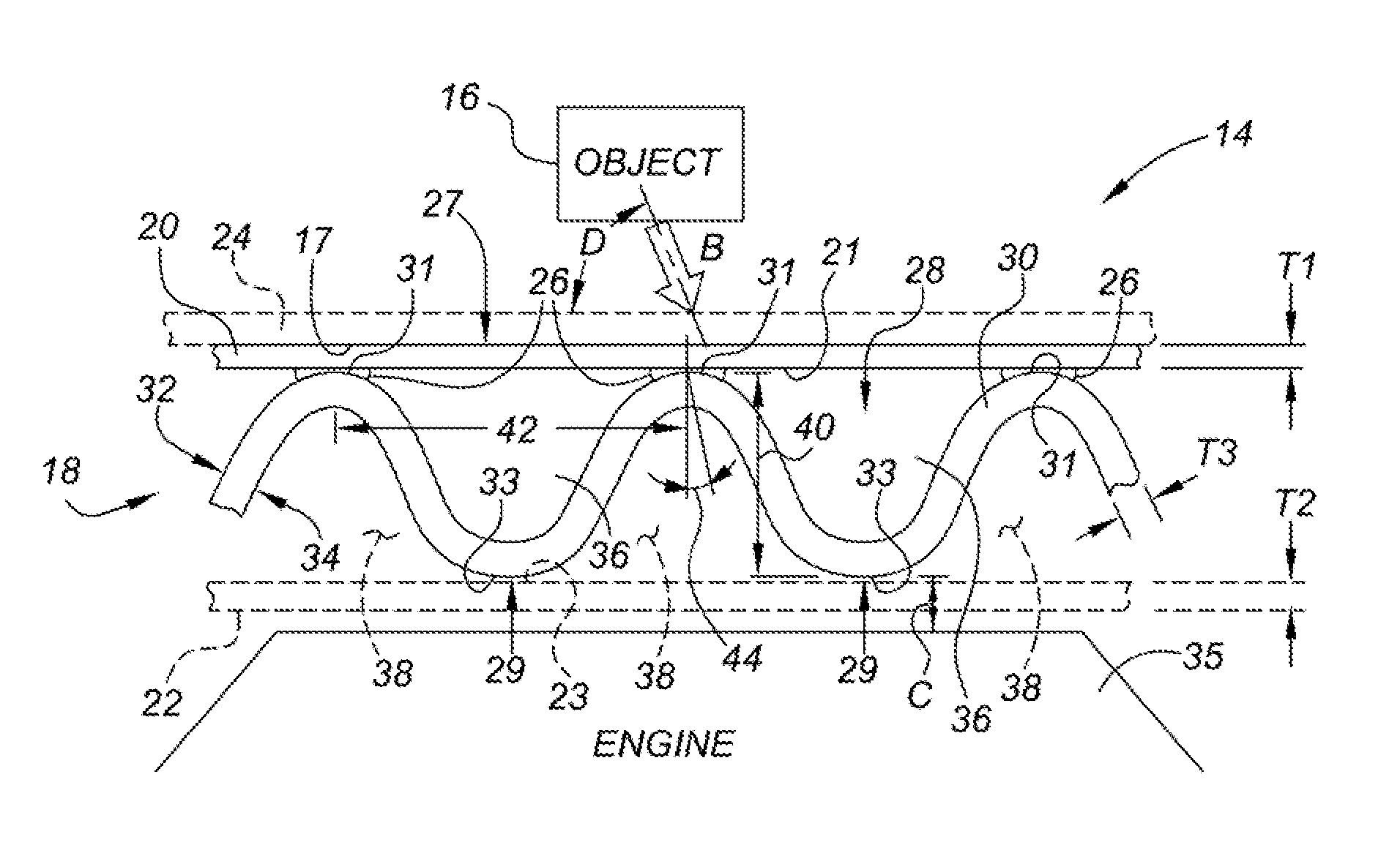
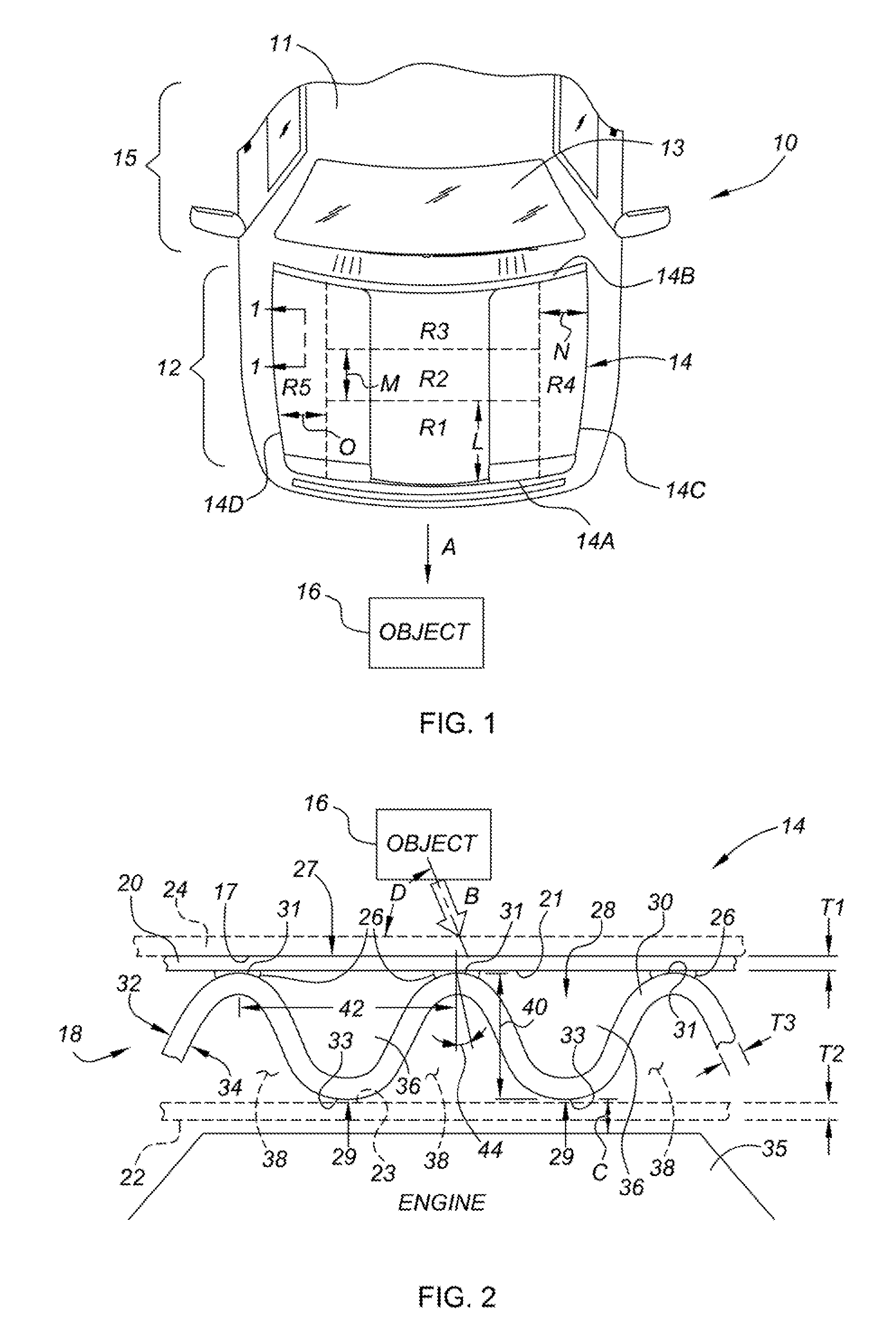
[0017]Referring to the Figures, wherein like reference numbers refer to the same or similar components throughout the several views, FIG. 1 is a plan view of an exemplary motor vehicle, identified generally as 10, having a vehicle body 11 that includes a moveable or actuatable energy-absorbing vehicle hood assembly (hereinafter “hood assembly 14”) spanning or covering an engine compartment 12 forward of a passenger compartment 15. Although the vehicle 10 is depicted in FIG. 1 as a standard coupe-type passenger car, the hood assembly 14 can be incorporated into any vehicle platform, such as sedan-type passenger cars, light trucks, heavy duty vehicles, etc.

[0018]The hood assembly 14 is operatively attached, secured, or mounted to the vehicle body 11, for example, by one or more peripheral hinges (not shown) positioned adjacently to a windshield 13. Ideally, the hood assembly 14 is sufficiently sized and shaped to provide a closure panel suitable for substantially covering and protecti...


PUM


Abstract

An energy-absorbing hood assembly for a vehicle includes an inner layer operatively secured to an upper layer having a first interface surface. The inner layer has opposing first and second surfaces defining a sinusoidal profile that is oriented to extend from the forward end of the vehicle towards the rearward end of the vehicle. The sinusoidal profile includes varying amplitudes and wavelengths along different regions of the hood assembly. The amplitudes and wavelengths are individually configured to provide regionally distinct predetermined levels of absorption and attenuation of kinetic energy imparted to the hood assembly by an object upon impact therebetween. Preferably, the hood assembly also includes a lower layer having a second interface surface; wherein the inner layer has a plurality of bonding surfaces attached to the first and second interface surfaces to thereby define a plurality of laterally oriented channels.

Description

TECHNICAL FIELD[0001]The present invention relates generally to vehicle front structures, and more specifically to energy-absorbing engine compartment hoods for increasing the deceleration of an object and reducing resultant forces transmitted thereto by the engine compartment hood upon impact therebetween, thereby minimizing the stopping distance of the object.BACKGROUND OF THE INVENTION[0002]Automotive vehicle bodies are typically constructed using stamped metal panels, which combine substantial overall strength and stiffness with a smooth, paintable exterior surface. With specific regard to vehicle hood panels (also referred to in the art as engine compartment hoods or bonnet structures), panel stiffness is often satisfied via the combination of a relatively high strength stamped metal outer or upper surface, referred to as an “A-surface”, coupled with a preformed inner or lower surface, referred to as a “B-surface”, supported by a series of engine-side or hat-section reinforceme...

Claims


Application Information

Patent Timeline
Patent Type & Authority Applications(United States)
IPC IPC(8): B60R21/02B62D25/10
CPCB62D25/105
Inventor WANG, JENNE-TAIDENG, BINGZHOU, QINGLIU, QIXIA, YONG
Owner GM GLOBAL TECH OPERATIONS LLC
Why Eureka
Try Eureka