Collapsible freestanding body armor support stand

a freestanding, article technology, applied in the direction of stands/trestles, dummies, show hangers, etc., can solve the problems of one or more components of the support stand failing, adding to the overall size, complexity and cost of the support stand, and not being particularly robus

Inactive Publication Date: 2009-03-19
BARRA MASSIMO
View PDF23 Cites 28 Cited by
  • Summary
  • Abstract
  • Description
  • Claims
  • Application Information

AI Technical Summary

Benefits of technology

[0011]In still further accordance with the invention, the support stand is provided with supplemental hanging bars or article support members that are pivotally mounted to another of the second and third support sections. In a manner similar to that described above, the supplemental article support members are selectively shiftable between a first or stowed configuration and a second or deployed configuration. In the deployed configuration, the supplemental article support members can be used to support tactical gear such as ammunition belts, canteens, web gear and the like. If required, the supplemental article support members could be utilized to provide additional support for the body armor or other items. In any case, each of the base members, article support members and supplemental article support members is provided with a latching mechanism that prevents inadvertent shifting between the deployed and stowed configurations.
[0012]In accordance with one aspect of the invention, the plurality of telescoping support sections includes a fourth section having provided thereon an extraction handle. The extraction handle enables a user to readily shift the support stand from the first configuration to the second configuration. Preferably, when in the collapsed configuration, the support stand has an overall length of approximately 13 inches and, when in the deployed configuration, the support stand has an overall length of approximately 46 inches. In this manner, any body armor supported therefrom will remain above the ground and free from dirt and other hazards. In the stowed position, the support stand readily fits within a storage bag for transport by, for example, military personnel.

Problems solved by technology

As the above-mentioned articles are typically not heavy, most collapsible stands are not particularly robust and are made from light gauge steel or aluminum.
The addition of any necessary bracing and other structure, as well as the need for stronger materials, adds to the overall size, complexity and cost of the support stand.
Hanging larger or heavier objects on these existing supports would result in failure of one or more components of the support.
While the layers of Kevlar® are resistant to ballistic forces, the outer shell will degrade, particularly if routinely exposed to the acid and moisture of soil.
In addition, the ceramic plates, while capable of withstanding impact forces from a 0.50 caliber round, are surprisingly fragile.
While this is readily accomplished when on a military base or law enforcement station, proper care of body armor in the field is often times difficult.
Locating a hook or other element that can support the weight of body armor, is not always possible.
Over time, simply hanging the body armor on a nail or other hook may result in damage to the outer shell and, if the nail or hook fails, damage to the ceramic plates may also result.
As noted above, existing collapsible supports are not designed to support heavy objects such as body armor, nor are they designed for combat or field conditions.
Therefore, small light-weight supports are not capable of supporting the weight of body armor while heavier, more robust supports cannot be readily transported by a soldier.
However, weight is always a concern to a foot soldier such that items which are too bulky or heavy are impractical.

Method used


Image

  • Collapsible freestanding body armor support stand
  • Collapsible freestanding body armor support stand
  • Collapsible freestanding body armor support stand

Examples


embodiment

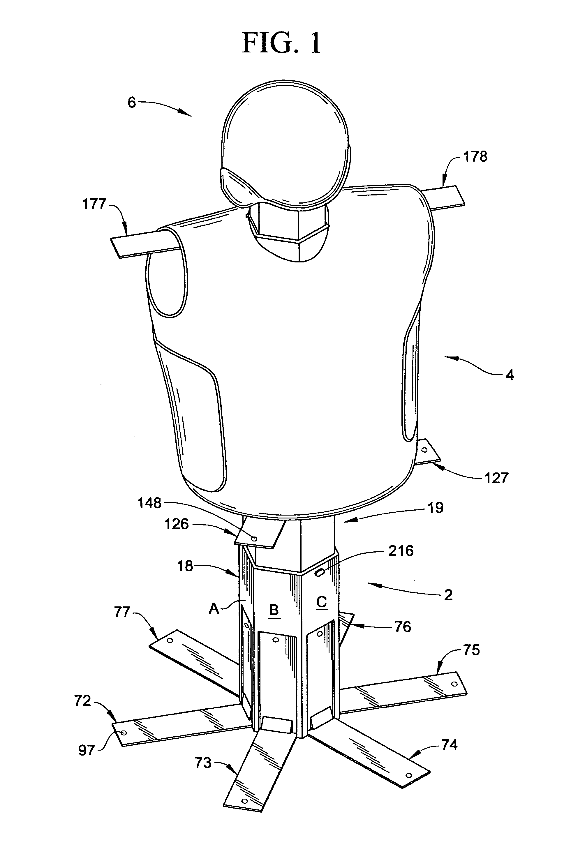
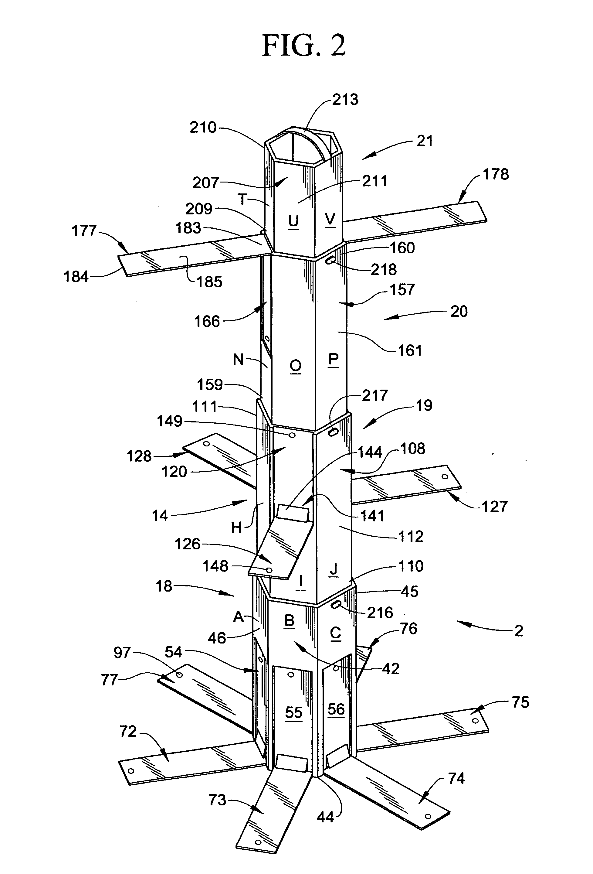
[0021]With initial reference to FIGS. 1 and 2, a collapsible, freestanding body armor support stand constructed in accordance with the present invention is generally indicated at 2. Support stand 2 is shown, in FIG. 1, supporting body armor 4 and a tactical helmet 6. Of course, support stand 2 could support various other items of gear, tactical or otherwise, such as web gear, uniforms, weapons, sunglasses and the like. As best shown in FIG. 2, body armor support stand 2 includes a main support member 14 formed from a plurality of telescoping, multi-faceted support sections. More specifically, main support member 14 includes a first support section 18, a second support section 19, a third support section 20 and a fourth support section 21. In the embodiment shown, each support section 18-21 is hexagonal in shape. However, various geometric shapes would also be acceptable.

[0022]Reference will now be made to FIGS. 2 and 3 in describing first support section 18 constructed in accordance...


PUM


Abstract

A collapsible, freestanding body armor support stand includes a main member having a plurality of telescoping sections that are shiftably interconnected and positionable between retracted and extended configurations. The support stand also includes a plurality of support bars that are pivotally mounted to the main member. The plurality of base members are shiftable between a stowed configuration, wherein the plurality of support members are substantially parallel to the main support member, and a deployed configuration, wherein the plurality of base members support the main support member upon a generally horizontal surface selectively shiftable between a stowed configuration and a deployed configuration. The hanging bars are designed to support, in the deployed configuration, body armor weighing up to 50 lbs or more.

Description

CROSS-REFERENCE TO RELATED APPLICATIONS[0001]The present application claims the benefit of U.S. Provisional Patent Application Ser. No. 60 / 924,876 entitled “Collapsible Freestanding Body Armor Support Stand” filed Jun. 4, 2007.BACKGROUND OF THE INVENTION[0002]1. Field of the Invention[0003]The present invention pertains to the art of article support stands and, more particularly, to a collapsible, freestanding article support stand adapted to support heavy body armor.[0004]2. Discussion of the Prior Art[0005]Collapsible, i.e., telescoping or folding, support stands are well known in the art. Small, easily transported, collapsible stands are used for supporting a wide array of articles such as intravenous bags, cameras, clothes and the like. As the above-mentioned articles are typically not heavy, most collapsible stands are not particularly robust and are made from light gauge steel or aluminum. However, collapsible supports for clothes, coats and the like require additional support...

Claims


Application Information

Patent Timeline
Patent Type & Authority Applications(United States)
IPC IPC(8): A47F7/19
CPCF16M11/28A47F8/00F16M2200/08F16M2200/066F16M11/046A47F5/04A47F5/10A47F7/00F16M2200/06
Inventor BARRA, MASSIMO
Owner BARRA MASSIMO
Why Eureka
Try Eureka