Automatic Lighting Control System And Method

Active Publication Date: 2009-03-19
IND TECH RES INST
View PDF15 Cites 75 Cited by
  • Summary
  • Abstract
  • Description
  • Claims
  • Application Information

AI Technical Summary

Benefits of technology

[0007]In the exemplary embodiments, the present disclosure may provi

Problems solved by technology

An over-lit and under-lit environment tires the eyes, and may even cause damages to the eyes.
Therefore, the appropriate luminance in an environment to prevent eyes from fatigue is an important issue.
Therefore, how to provide a comfortable en

Method used


Image

  • Automatic Lighting Control System And Method
  • Automatic Lighting Control System And Method
  • Automatic Lighting Control System And Method

Examples


Embodiment Construction

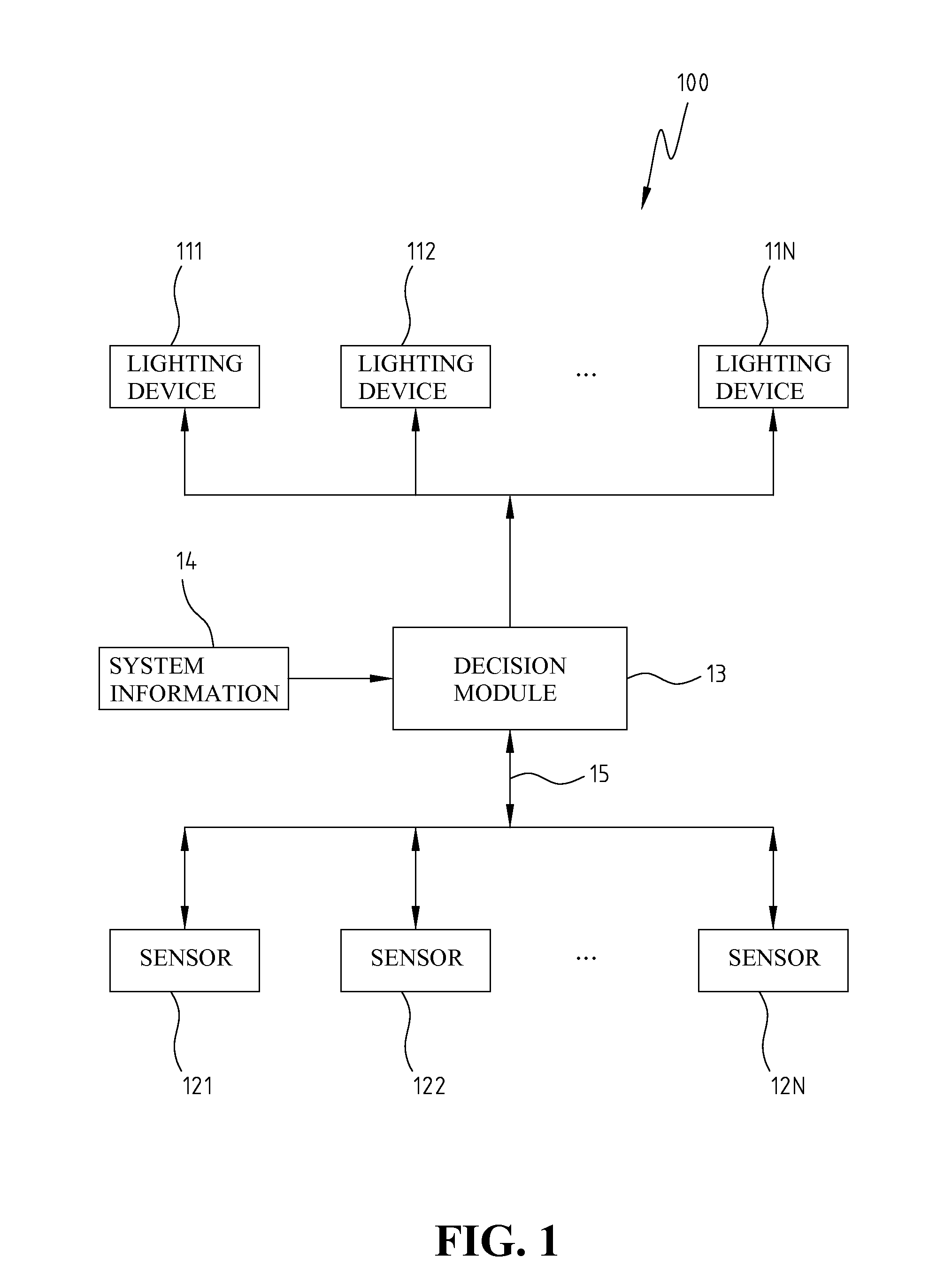
[0024]FIG. 1 shows a schematic view of an exemplary automatic lighting control system, consistent with certain embodiments of the present disclosure. Referring to FIG. 1, automatic lighting control system 100 may comprises at least a lighting device 111-11N, at least a sensor 121-12N, and a decision module 13. Each of lighting devices 111-11N is adjustable, and has a remote control function. Sensors 121-12N are automatically configured as a wireless sensor network to detect the luminance for a system environment and to reports the luminance to a decision module 13 through a wireless network 15. Decision module 13 dynamically adjusts each of lighting devices 111-11N to a suitable luminance based on system information, the reported luminance from sensors 121-12N, and the users' demands. The suitable luminance for each lighting device may allow the users to feel comfortable environmental lighting sources.

[0025]Decision module 13 may adjust and control lighting devices 111-11N by a remo...


PUM


Abstract

Disclosed is directed to an automatic lighting control system and method. The system includes at least a lighting device, at least a sensor, and a decision module. Each lighting device is adjustable and has a remote control function. A wireless sensor network is configured by the one or more sensors. Each sensor may sense a corresponding luminance and returns the luminance to the decision module in a wireless manner. The decision module may dynamically adjust one or more lighting devices to a suitable luminance by referring to system information, the returned luminance and user's demands.

Description

FIELD OF THE INVENTION[0001]The present invention generally relates to an automatic lighting control system and method.BACKGROUND OF THE INVENTION[0002]An over-lit and under-lit environment tires the eyes, and may even cause damages to the eyes. Therefore, the appropriate luminance in an environment to prevent eyes from fatigue is an important issue. A Central Standard Bureau defines regulations on the required illumination for different occasions. For example, the illumination for a classroom is 200-750 Lux, 300-1500 Lux for the blackboard, more than 500 Lux for the desk top, 750-1500 Lux for offices and designing room, and 75-150 Lux for the break room and warehouse.[0003]In addition to the sufficient illumination, the distribution of the illumination is also important, called the uniformity of luminous brightness distribution. The more uniformly distributed the light, the less stress on the eyesight. Therefore, how to provide a comfortable environment with appropriate and balance...

Claims


Application Information

Patent Timeline
IPC IPC(8): G05B19/00
CPCH05B37/0218Y02B20/46H05B37/0272H05B47/11H05B47/19Y02B20/40
Inventor PAN, MENG-SHIUANCHEN, YEN-ANNCHIEN, TING-CHOULEE, YUEH-FENGTSENG, YU-CHEE
Owner IND TECH RES INST
Why Eureka
Try Eureka