Multi-functional side rear view mirror for vehicles

Inactive Publication Date: 2009-03-26
HU TIANYI
View PDF4 Cites 15 Cited by
  • Summary
  • Abstract
  • Description
  • Claims
  • Application Information

AI Technical Summary

Benefits of technology

[0007]This invention allows the driver of a typical vehicle to have a broader view of the road by presenting a vehicular left side rear view mirror that has at least one camera installed on. The lens of the camera is facing the direction of the front of the vehicle, so that more images behind above-mentioned Car B can be captured without having the driver to stick his/her head out of the window. The images captured by the camera will be displayed on the glass mirror of the same rear view mirror unit, implemented by

Problems solved by technology

In this situation, cars running straight behind Car B cannot be seen by the driver of Car A. If the left-turn is made

Method used


Image

  • Multi-functional side rear view mirror for vehicles
  • Multi-functional side rear view mirror for vehicles
  • Multi-functional side rear view mirror for vehicles

Examples


Embodiment Construction

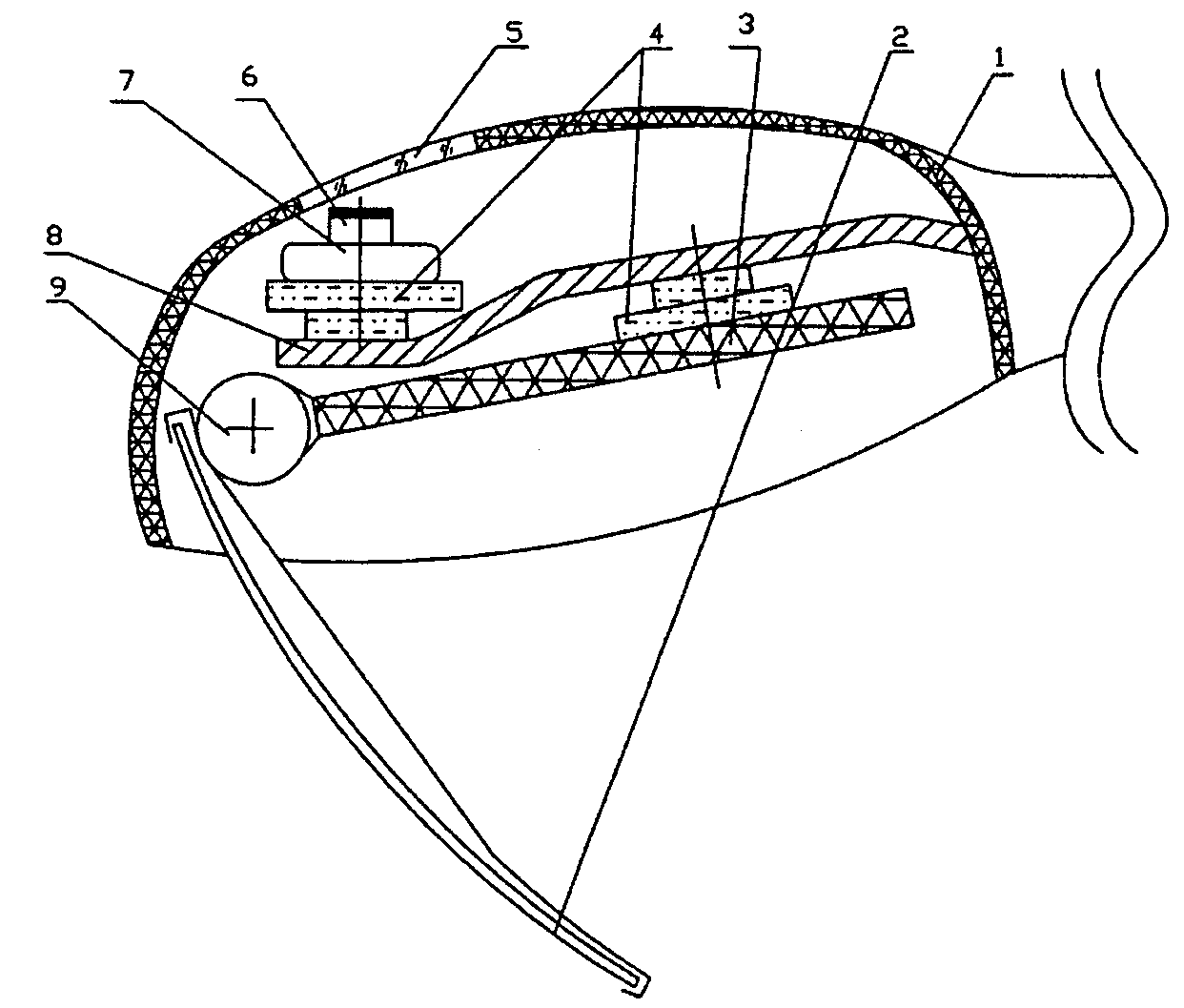
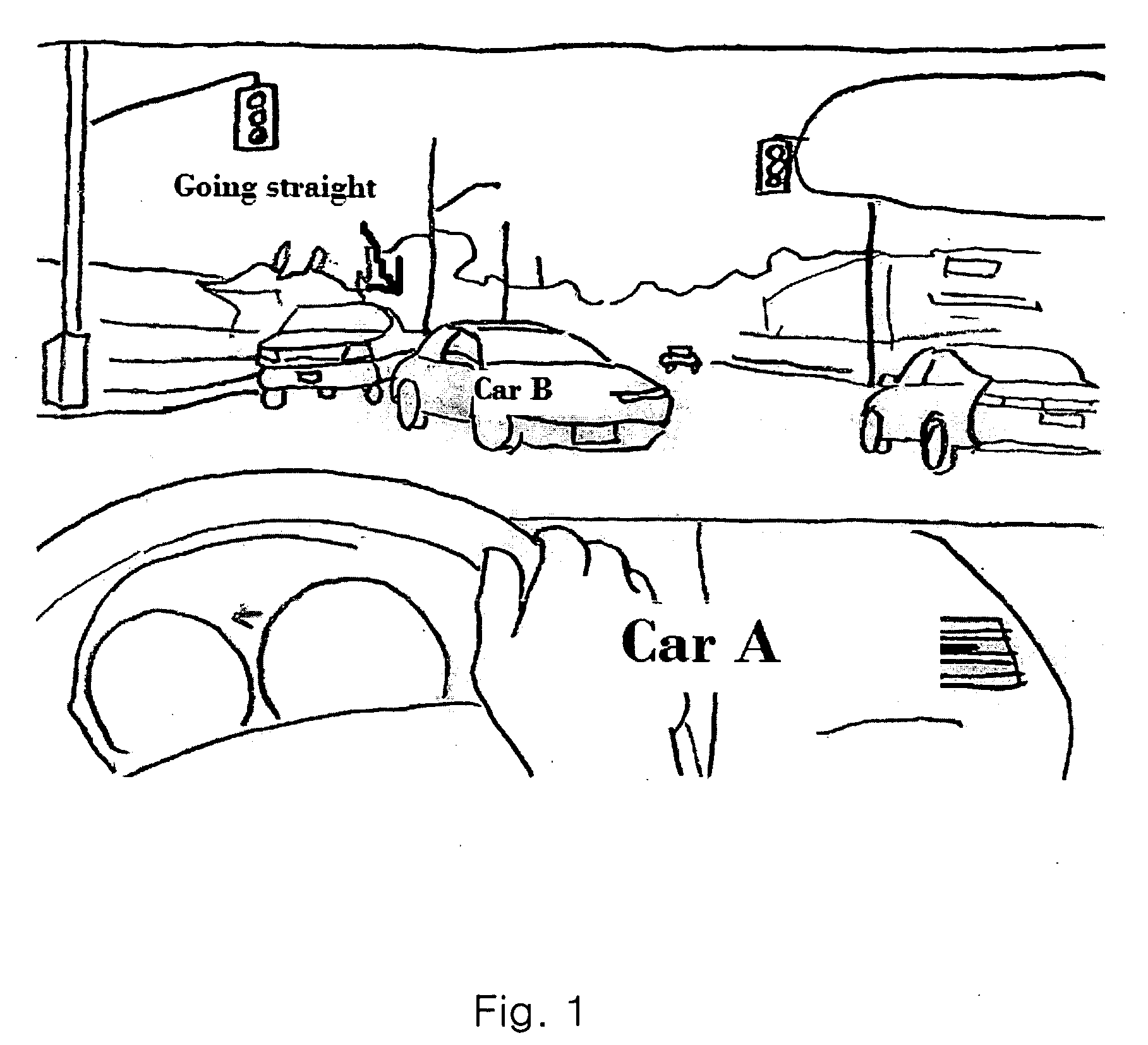
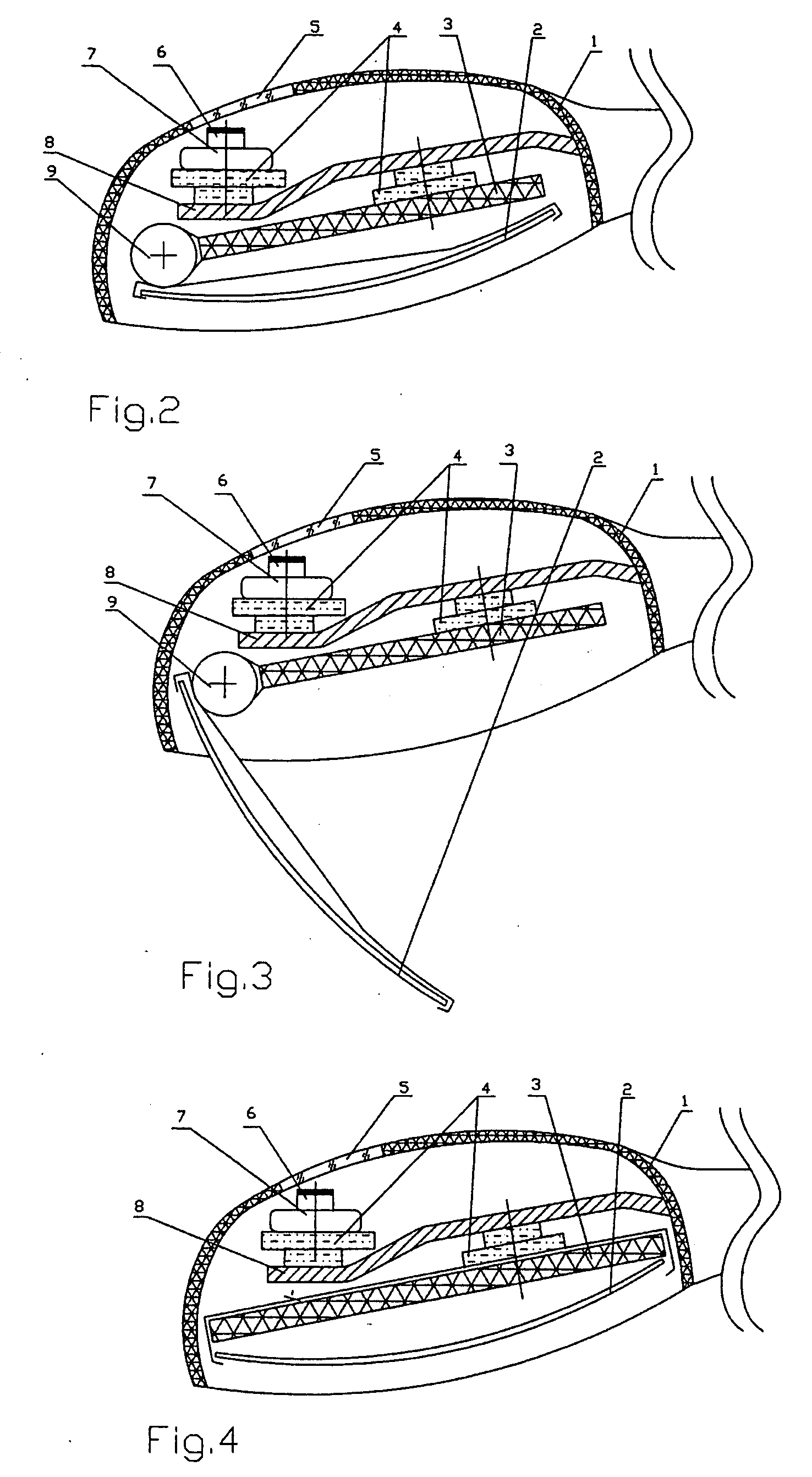
[0022]This invention has a digital camera installed within the case of the rear view mirror system, and the position of the camera is close to the tip of the casing unit, which is the best place to observe the cars that are going straight from the other direction behind Car B. A hole is made on the casing unit where the camera is, and covered by a piece of transparent protective board so the lens of the camera is exposed to light. The fixed supporting board separates the whole rear view system into two portions, one in the front and one in the back. The direction adjusting device for the camera (which is the same as the direction adjusting device for the one-way mirror ) is installed on the front side of the fixed supporting board(as shown in FIG. 2), the direction adjusting device for the one-way mirror is installed on the other side of the fixed supporting board. These adjusting devices are commonly found in existing side rear view mirrors. There is also one video display monitor ...


PUM


Abstract

A side rearview mirror with one-way mirror, video display monitor and camera for the driver to easily and safely view the traffic that is going straight from the other direction at an intersection while trying to make a left turn, while at the same time not losing the function of a regular rearview mirror. The camera is facing the front and the video monitor is immediate placed behind the one way mirror to achieve said functions.

Description

CROSS-REFERENCE TO RELATED APPLICATIONS[0001]This application claims the benefits of USPTO provisional utility application No. 60 / 994,997 filed on Sep. 25, 2007. The content of which is hereby incorporated into this application.STATEMENT REGARDING FEDERALLY SPONSORED RESEARCH OR DEVELOPMENT[0002]Not applicableREFERENCE TO A SEQUENCE LISTING, A TABLE OR A COMPUTER PROGRAM LISTING COMPACT DISK APPENDIX[0003]Not applicableBACKGROUND OF THE INVENTION[0004]On most major roads in the world, cars (Car A) making a left turn must wait for cars that are going straight from the opposite direction when the green light is on. If there was a Car B waiting to make a left turn from the other side of the intersection on the other direction too, the Car A driver's sight will be blocked by Car B, as shown in FIG. 1. In this situation, cars running straight behind Car B cannot be seen by the driver of Car A. If the left-turn is made without being aware of vehicles going straight behind Car B, an accide...

Claims


Application Information

Patent Timeline
IPC IPC(8): H04N7/18
CPCB60R1/00B60R1/06B60R1/12B60R11/0235B60R11/04H04N7/183B60R2011/0033B60R2011/004B60R2011/008B60R2011/0094B60R2300/8026B60R2001/1253
Inventor HU, TIANYI
Owner HU TIANYI
Why Eureka
Try Eureka