Turbomachine nozzle cowl having jet noise reduction patterns

a technology of nozzles and nozzles, which is applied in the field of nozzles, can solve the problems of unfavorable increase in the amount of turbulence in the near field of exhaust, negative influence of increase on any potential for reducing noise, and present drawbacks, and achieve the effect of reducing the noise of the j

Inactive Publication Date: 2009-04-02
SN DETUDE & DE CONSTR DE MOTEURS DAVIATION S N E C M A
View PDF6 Cites 8 Cited by
  • Summary
  • Abstract
  • Description
  • Claims
  • Application Information

AI Technical Summary

Benefits of technology

[0008]The present invention seeks to remedy the above-mentioned drawbacks by providing a cowl for a separate-stream nozzle, which cowl enables mixing between the hot and cold streams to be made more effective so as to reduce the jet noise at the outlet from the nozzle, both at high frequencies and at low frequencies.

Problems solved by technology

The nub of the problem lies in controlling the characteristics of the mixing that is to be obtained between the hot and the cold streams, it being understood that one of the consequences of mixing too roughly is an undesirable increase in the amount of turbulence in the near field of the exhaust.
Such an increase has a negative influence on any potential for reducing noise that might be obtained in mixing zones that are further away.
Although the above-mentioned patterns do indeed encourage mixing between the streams, they nevertheless present drawbacks.
This gives rise to mixing between the streams that is not very effective, in particular in zones that are further away from the exhaust.
In the vicinity of each of those patterns, the intensities of the two vortices that are generated are different, such that the vortices do not compensate over the entire circumference of the cowl.
However, in addition to such patterns obtaining acoustic improvement at low frequencies, they also give rise to an increase in noise levels at high frequencies.

Method used


Image

  • Turbomachine nozzle cowl having jet noise reduction patterns
  • Turbomachine nozzle cowl having jet noise reduction patterns
  • Turbomachine nozzle cowl having jet noise reduction patterns

Examples


Embodiment Construction

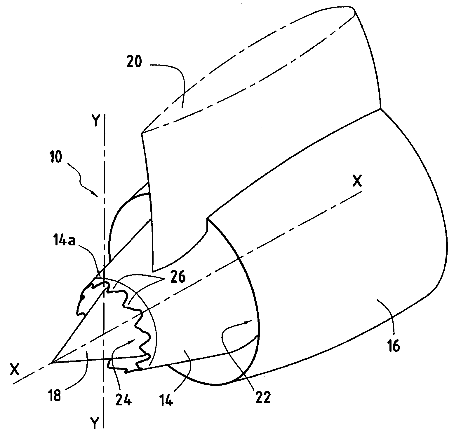
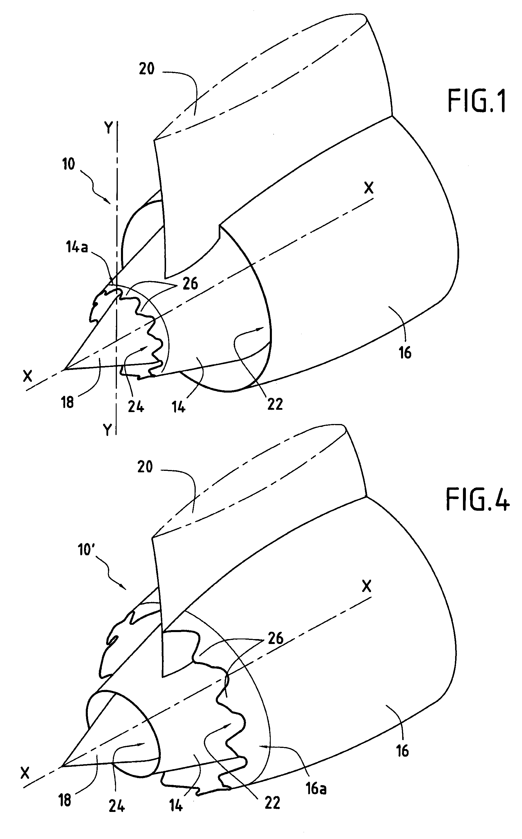
[0025]FIG. 1 is a perspective view of a separated stream nozzle 10 of a turbomachine. The nozzle 10 is of axially-symmetrical shape about its longitudinal axis X-X, and it is typically formed by a primary cowl 14, a secondary cowl 16, and a central body 18 centered on the longitudinal axis X-X of the nozzle.

[0026]The primary cowl 14 is of substantially cylindrical or frustoconical shape, and it extends around the longitudinal axis X-X of the nozzle. The central body 18 is disposed concentrically inside of the primary cowl 14 and it is terminated by a portion that is substantially conical.

[0027]The secondary cowl 16 is likewise of substantially cylindrical or frustoconical shape and it surrounds the primary cowl 14 concentrically, extending around the longitudinal axis X-X of the nozzle.

[0028]It should be observed that the longitudinal axis X-X of the nozzle coincides with the longitudinal axes of the primary and secondary cowls 14 and 16.

[0029]The separated-stream nozzle as defined ...


PUM


Abstract

The invention relates to a cowl for a turbomachine nozzle, the cowl including a plurality of repetitive patterns disposed to extend a trailing edge of said cowl and spaced circumferentially apart from one another. Each pattern is in the form of a quadrilateral having a base that is formed by a portion of the trailing edge of the cowl and two vertices that are spaced downstream from the base and that are connected thereto via two sides, each side having the shape of a parabola. Each pattern is asymmetrical relative to a midplane of the pattern containing a longitudinal axis of said cowl, and it comprises a first portion inclined radially towards the inside of the cowl, and a second portion inclined radially towards the outside of the cowl.

Description

BACKGROUND OF THE INVENTION[0001]The present invention relates to the general field of nozzles fitted to turbomachines. More particularly, it relates to a separate-stream nozzle in which at least one of the cowls is provided with patterns for the purpose of reducing the jet noise generated at the outlet from the nozzle.[0002]In general, a separate-stream nozzle for a turbomachine comprises a primary cowl, a secondary cowl disposed concentrically around the primary cowl so as to define a first annular channel for passing the flow of an outer stream (or cold stream), and a central body disposed concentrically inside of the primary cowl so as to define a second annular channel for passing the flow of an inner stream (or hot stream).[0003]One known technique for reducing jet noise at the outlet from such a nozzle is to encourage mixing between the hot and cold streams coming from the turbomachine. The nub of the problem lies in controlling the characteristics of the mixing that is to be...

Claims


Application Information

Patent Timeline
Patent Type & Authority Applications(United States)
IPC IPC(8): F02K1/44F01N1/08F01N1/14
CPCF02K1/386F05D2250/16F02K3/06F02K1/48
Inventor AEBERLI, SEBASTIEN JEAN-PAULLOHEAC, PIERRE PHILIPPE MARIETHOMAS, STEPHANE JACQUES FRANCOISVUILLEMIN, ALEXANDRE ALFRED GASTONZEGGAI, KAMEL
Owner SN DETUDE & DE CONSTR DE MOTEURS DAVIATION S N E C M A
Why Eureka
Try Eureka