Vacuum high pressure filling equipment

Inactive Publication Date: 2009-04-02
MIKADO TECHNOS
View PDF8 Cites 8 Cited by
  • Summary
  • Abstract
  • Description
  • Claims
  • Application Information

AI Technical Summary

Benefits of technology

[0004]A first object of the present invention is to provide a vacuum / high pressure filling apparatus which can increase a filling rate and shorten an impregnating time period and which thus can shorten the working time period and the vacuum / high pressure filling time by making the movement of the a filling liquid from a filling liquid vessel unnecessary, through employing a construction in which after a porous workpiece to be processed is deaerated inside a hermetic partition chamber unit under vacuum, the workpiece is immersed in the filling liquid of the liquid vessel inside the hermetic partition chamber unit, while the deaerated state is being kept; the filling material is forcedly filled into fine pores of the porous workpiece through applying a high pressure to the filing liquid in the immersing state.

Problems solved by technology

However, the above conventional first vacuum filling apparatus has drawbacks that the filling rate is low and it takes a long time to perform the vacuum impregnation.
So, it takes an extra equipment and time.
Accordingly, it was difficult to shorten the working time.

Method used


Image

  • Vacuum high pressure filling equipment
  • Vacuum high pressure filling equipment
  • Vacuum high pressure filling equipment

Examples


first embodiment

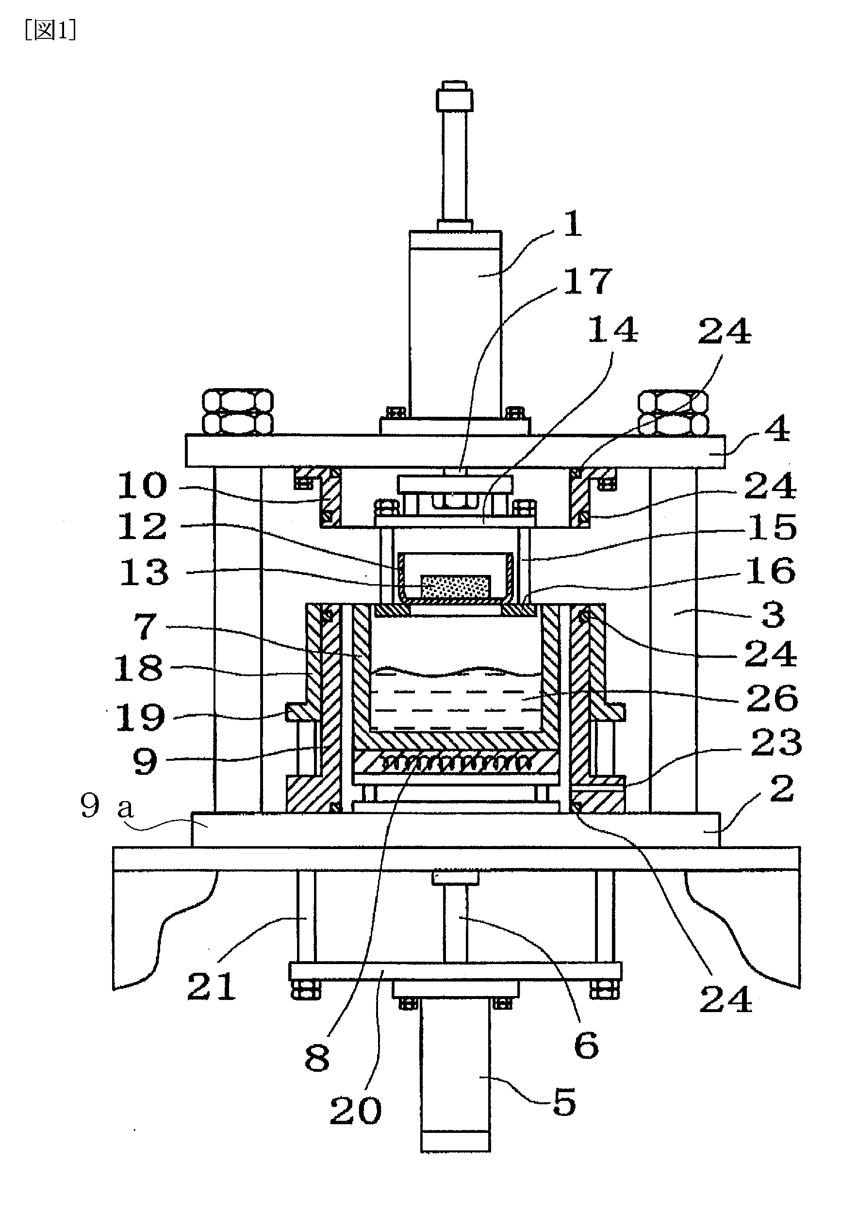
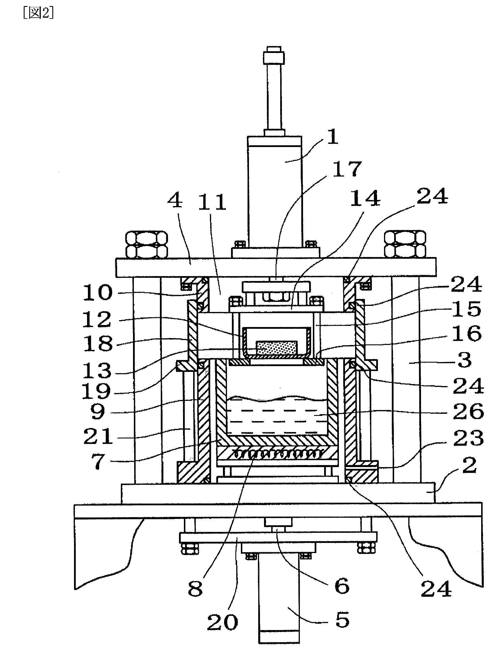
[0050]FIGS. 1 to 3 show a first embodiment according to the present invention. FIG. 1 is a front view schematically showing a state in which a container for a workpiece to be processed can be moved in and out. FIG. 2 is a front view schematically showing a deaerating state. FIG. 3 is a front view schematically showing a pressure filling state. In FIGS. 1 to 3, a hang-down cylinder 1 is attached onto an attachment plate 4 which is horizontally provided over head portions of posts 3 erected at four corners of a base table 2, and a rod 17 extends downwardly through the attachment plate 4. On the other hand, a push-up cylinder 5 is upwardly attached on a lower side of the base table 2. The push-up cylinder 5 is coaxially arranged with the hang-down cylinder 1, and a leading end of its rod 6 is fixed to the lower face of the base table 2, so that the rod 6 is extended and shrunk to vertically move the push-up cylinder 5 itself. The push-up cylinder 5 ascends the below-mentioned sliding f...

second embodiment

The second embodiment is the same as the first one except for the following points.

[0067]A hang-down member 14′ is attached to a lower end portion of a rod 17 of a hang-down cylinder 1, and an elevator table 16 is fixedly connected to a lower face of the hang-down member 14′ through plural connection rods 15. An upper frame 10′ is hung down from a attachment plate, surrounding the outer side of the connection rods 15. As shown in FIG. 4, an upper end portion of a lower moving frame 9 and a lower end portion of the upper frame 10′ are designed to be closely engaged with each other. A liquid vessel 7 is fixed, in a floated manner, to a liquid vessel receiving table 8 equipped with a heater, and the lower moving frame 9 is arranged along the outer periphery of the liquid vessel receiving table 8. An outer flange 19 of the lower moving frame is fixedly connected to a push-up plate 20 of a push-up cylinder 5 via plural connection rods 21, and the lower moving frame 18 is vertically moved...

third embodiment

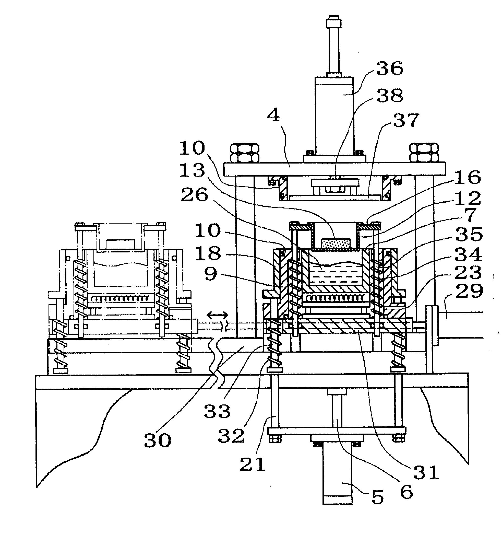
[0069]FIG. 5 is a front view schematically showing a third embodiment in which automatization is performed by using a slide table.

[0070]That is, a workpiece container is designed as an automated transportation system, so that the porous workpiece can be moved in and out from the workpiece container outside the machine. Specifically, a slide table 31 (corresponding to the base table 2), which is slid on a rail 30 by means of a slide cylinder 29, is used, the lower fixed frame 10, the sliding frame 18, the liquid vessel 7, the workpiece container 12 and the elevator table 16 are reciprocated laterally, and the slide frame 18 is vertically moved via intermediate transmission rods 33 which are to be returned downwardly by return springs 32, and the elevator table 16 is ascended via leg rods 35 which are returned upwardly by return springs 34. Further, the elevator table 16 is moved downwardly by a push plate 37 which is vertically moved by a push up-and-down cylinder 36. However, the sl...


PUM

PropertyMeasurementUnit
Fractionaaaaaaaaaa
Fractionaaaaaaaaaa
Fractionaaaaaaaaaa

Abstract

The present invention proposes a vacuum / high pressure filling apparatus which can improve the filling rate and shorten the impregnating time period in immersing a porous workpiece into a filling liquid. The vacuum / high pressure filling apparatus includes: an openable and closable hermetic partition chamber unit constituted by two upper and lower split partition wall unit portions, a partition chamber unit opening and closing mechanism to open and close the partition chamber unit, a vacuum suction opening and a pressurizing opening provided for the partition chamber unit, a liquid vessel arranged in the partition chamber unit to receive a filling liquid, a holder arranged, in the partition chamber unit, for the porous workpiece, an elevator unit to move the filling liquid in the liquid vessel and the porous workpiece relative to each other inside the partition chamber unit so as to immerse the porous workpiece into the filling liquid in the liquid vessel and pull up the workpiece from the filling liquid. When the partition chamber unit opening and closing mechanism brings the two upper and lower split partition wall unit portions into hermetic contact with each other, the partition chamber unit is closed and sealed. When the partition chamber opening and closing mechanism spaces the two upper and lower split partition wall unit portions from each other, the partition chamber unit is opened. By using the vacuum / high pressure filling apparatus according to the present invention, composite materials such as lubricant-impregnated metals, thermosetting resin-impregnated cast metals, etc. can be obtained.

Description

TECHNICAL FIELD[0001]The present invention relates to vacuum / high pressure filling apparatuses which inside a hermetic partition chamber unit, forcedly deaerates under vacuum pores or holes of a workpieces to be processed, which is finely porous or has through-pores or through-holes or blind pores or holes (bottomed pores or holes) (hereinafter referred to as “porous workpiece” in this specification), immerses the workpiece in a filling material such as a filling liquid or fluid or a powder-mixed liquid, forcedly fills the filling material into the workpiece under pressure with air or a gas, and thereby obtains a composite material having high gastightness and functionality. Further, the present invention relates to a vacuum / high pressure filling apparatus which inside a hermetic partition chamber unit, forcedly deaerates under vacuum a fluid material to be processed, and mixes a mixed gas into the fluid material in an atmosphere filled with the mixed gas at a high pressure. Further...

Claims


Application Information

Patent Timeline
IPC IPC(8): B05C5/00A23L5/30
CPCB22D19/00B22D19/14B22F3/26B22F2998/00B22F3/003
Inventor ITO, HIDETOSHI
Owner MIKADO TECHNOS
Why Eureka
Try Eureka