System for treating money in an automatic vending machine

a vending machine and automatic technology, applied in the field of automatic vending machine treatment system, can solve the problems of reducing profit, difficulty in dealing with the use of various kinds of money, and lowering the utilization of automatic vending machines, and achieve the effect of convenient us

Inactive Publication Date: 2009-04-02
KABUSHIKI KAISYA I S ELECTRONICS +1
View PDF1 Cites 4 Cited by
  • Summary
  • Abstract
  • Description
  • Claims
  • Application Information

AI Technical Summary

Benefits of technology

[0019]According to the fourth aspect of the invention, the VTS system and the MDB system can be used in a multiplicity of ways with the communication means as a boundary, and can be widely applied to the regions without receiving limitation depending upo

Problems solved by technology

The present invention solves the problem in that a system for treating money in an automatic vending machine imposes a limitation on the kinds of bills (amount of money) and on the number of pieces of bills that can be thrown in d

Method used


Image

  • System for treating money in an automatic vending machine
  • System for treating money in an automatic vending machine
  • System for treating money in an automatic vending machine

Examples


embodiment 1

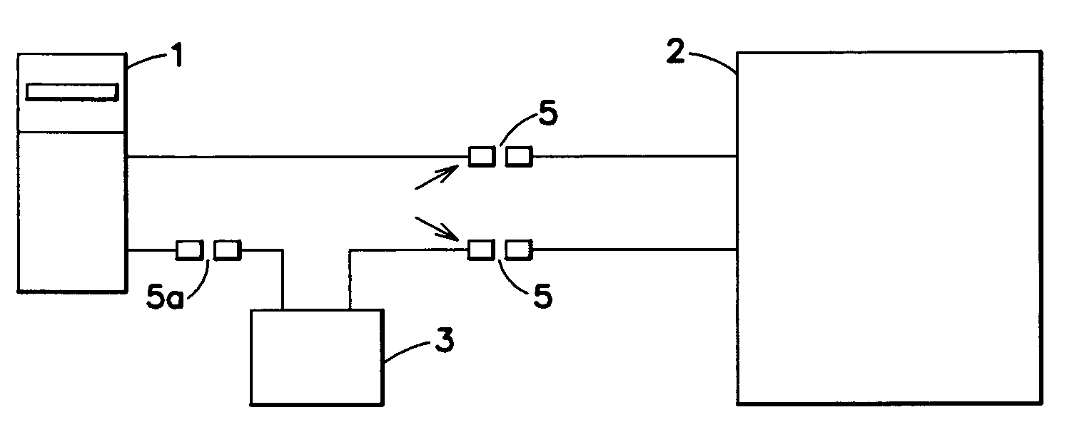
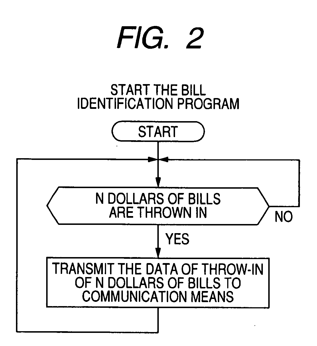
[0030]Next, a first embodiment of the invention will be described with reference to FIGS. 1 to 3. FIG. 1 is a block diagram illustrating a first embodiment of the invention, FIG. 2 is a flowchart illustrating a program of a device for identifying the bills, and FIG. 3 is a flowchart illustrating a program of communication means.

[0031]In these drawings, reference numeral 1 denotes a device for identifying the bills. The device 1 for identifying the bills is, usually, mounted on the inner surface of a front door of an automatic vending machine. A port for throwing the bills in is opened outward through the front door, enabling the bills to be thrown in. Reference numeral 2 denotes a controller in the automatic vending machine. The controller 2 is electrically connected to the device 1 for identifying the bills through a communication circuit of a VTS system, and those data related to the throw-in of bills only are not transmitted to the controller 2.

[0032]In the drawings, further, ref...

embodiment 2

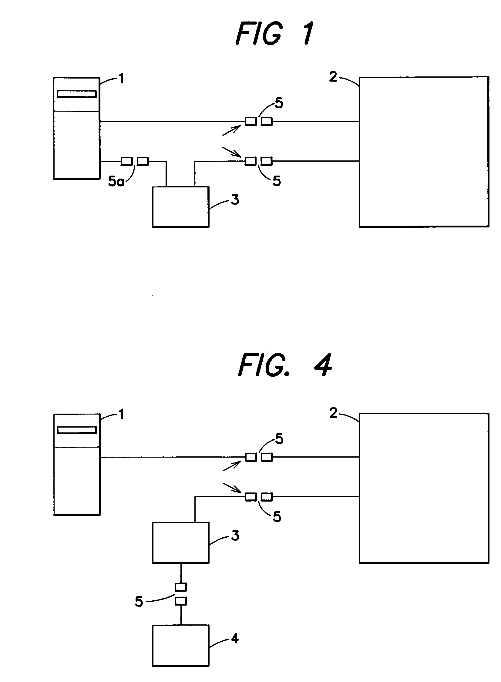
[0035]Next, a second embodiment of the invention will be described with reference to FIGS. 4 to 6. FIG. 4 is a block diagram illustrating the second embodiment of the invention, FIG. 5 is a flowchart illustrating a program of the device for identifying the bills, and FIG. 6 is a flowchart illustrating a program of communication means. Portions common to those of the first embodiment are denoted by the same reference numerals, but their detailed description is not repeated.

[0036]In the case of the second embodiment, too, the device 1 for identifying the bills is electrically connected to the controller 2 of the automatic vending machine based on the VTS system by using a communication circuit. The communication means 3 is electrically connected to the controller 2 also based on the VTS system but using another communication circuit.

[0037]In the second embodiment, the communication means 3 is not connected to the device 1 for identifying the bills through the communication circuit. In...

embodiment 3

[0041]Next, a third embodiment of the invention will be described with reference to FIGS. 7 to 9. FIG. 7 is a block diagram illustrating the third embodiment of the invention, FIG. 8 is a flowchart illustrating a program of the device for identifying the bills, and FIG. 9 is a flowchart illustrating a program of communication means. Portions common to those of the first embodiment and the second embodiment are denoted by the same reference numerals, but their detailed description is not repeated.

[0042]According to the third embodiment, communication means 3 is interposed as a communication circuit of the VTS system between the device 1 for identifying the bills and the controller 2, and the device 4 for treating the coins is connected to the communication means through a communication circuit of the MDB system. In the drawing, reference numeral 5b denotes 8-pin connectors of the MDB. That is, the device 4 for treating the coins and the device 1 for treating the bills are both connec...


PUM


Abstract

A system for treating money in an automatic vending machine imposes a limitation on the kinds of bills (amount of money) and on the number of pieces of bills that are to be thrown in due to the program of the controller in the automatic vending machine, making it often difficult to cope with the use of various kinds of moneys, lowering the utilization of the automatic vending machines and decreasing the profit. To overcome the above problem, a device for treating the coins that are thrown in is electrically connected to communication means which receives and transmits data related to the throw-in of coins, and the communication means, the device for identifying the bills that are thrown in and the controller in the automatic vending machine are electrically connected together. Further, the primary side and the secondary side of the communication means select either a VTS system or a MDB system and, particularly, the primary side is of the VTS system and the secondary side is of the MDB system. The controller is equipped with a change-over switch for changing the price of a good to be sold and for freely setting the kinds of bills that can be used, the number of pieces thereof and a combination thereof, and a change is discharged within a range set by the device for treating the coins.

Description

BACKGROUND OF THE INVENTION[0001]1. Field of the Invention[0002]This invention relates to a system for treating money in an automatic vending machine and, particularly, to a system for treating money in an automatic vending machine employing a VTS system or an MDB system.[0003]2. Description of the Related Art[0004]In the conventional systems for treating money in the automatic vending machines of the VTS system and the MDB system, a device for identifying the bills thrown into a controller in the automatic vending machine and a device for treating the coins are electrically connected together, and data related to the throw-in of money from these devices are sent to the controller to indicate the sum of moneys that are thrown in.[0005]In the device for identifying the bills in the conventional systems for treating money, the kinds and amounts of bills that can be thrown in are limited by a maximum value or a minimum value, and the bills that are thrown in within the limitation are j...

Claims


Application Information

Patent Timeline
IPC IPC(8): G07F9/00
CPCG07F9/08G07F9/026
Inventor ISHIWATA, YOSHIKAZU
Owner KABUSHIKI KAISYA I S ELECTRONICS
Why Eureka
Try Eureka