

Rotating Electrical Machine and Method for Manufacturing the Same
a technology of rotating electrical machines and manufacturing methods, which is applied in the direction of windings, dynamo-electric components, and embedding prefabricated windings, etc., and can solve the problems of unduly difficult manufacturing process of rotating electrical machines and lowering coil insulation
- Summary
- Abstract
- Description
- Claims
- Application Information
AI Technical Summary
Problems solved by technology
Method used
Image

Examples
first embodiment
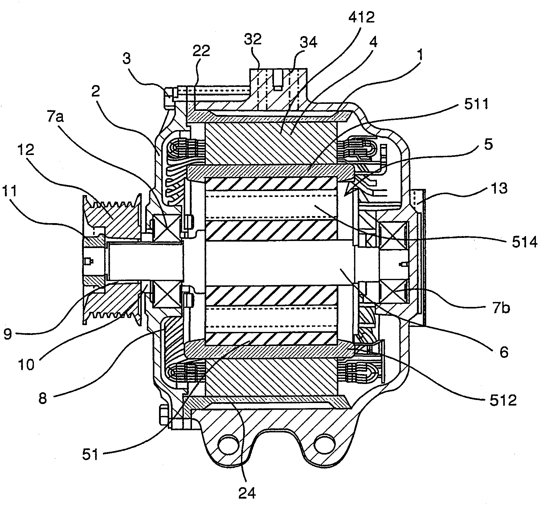
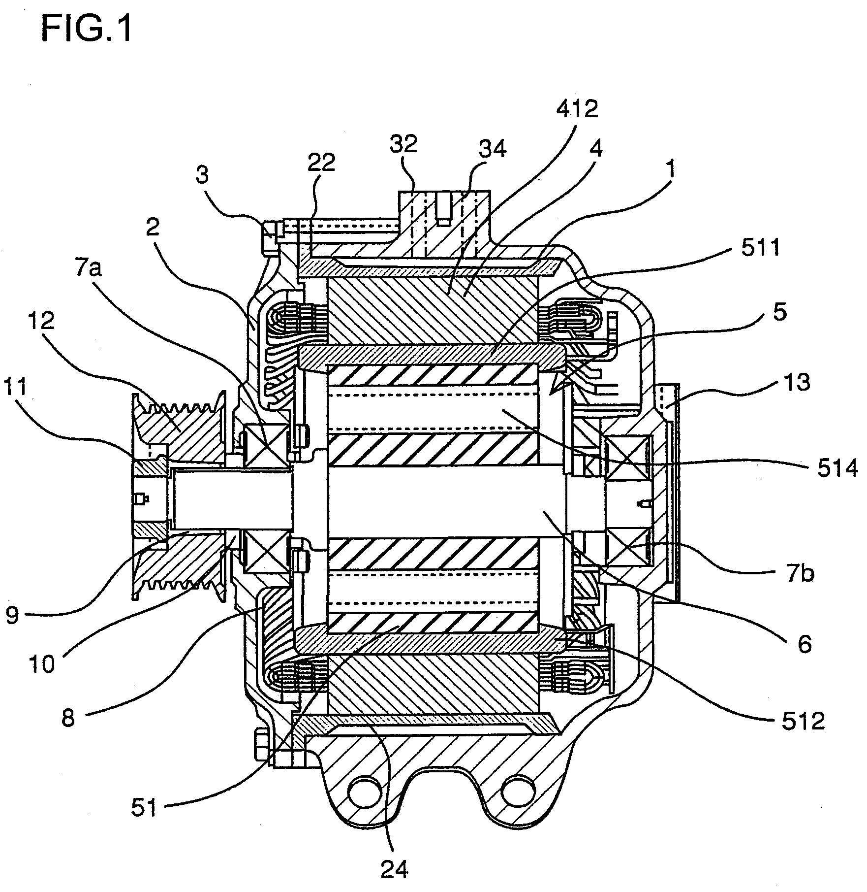
[0056]The following is a description of a rotating electrical machine achieved in the first embodiment of the present invention and a manufacturing method that may be adopted when manufacturing a stator in the rotating electrical machine.
[0057]The following explanation is provided by assuming that the rotating electrical machine to be described below in reference to the first embodiment of the present invention is a rotating electrical machine used in a hybrid vehicle.
[0058]It is to be noted that the rotating electrical machine achieved in the embodiment, to be used in a hybrid vehicle, fulfills both a function as a drive motor for driving the wheels and a function of a dynamo-electric generator that generates power as the wheels rotate. The rotating electrical machine is configured so as to allow either the motor function or the generator function to be selected in correspondence to the traveling state of the vehicle.
[0059]Before describing the manufacturing method that may be adop...
second embodiment
[0195]Next, in reference to FIG. 18, the stator 4 according to the second embodiment is described in detail.
[0196]FIG. 18 is an enlarged sectional view of stator slots at the stator 4 achieved in the second embodiment, taken over a plane perpendicular to the rotational axis.
[0197]It is to be noted that the same terms and reference numerals are assigned to components and portions identical to those in the first embodiment.
[0198]Once the stator coil 413 is inserted in the slots 411, the holding members 4162 are inserted further inward relative to the slot insulators 4181 in the slots, along the direction extending along the rotational axis, as shown in FIG. 18.
[0199]The holding members 4162, inserted further inward relative to the slot insulators 4181, each include two folded ends located at the two endpoints along the width-wise direction. Namely, the holding members 4162 assume a substantially U-shape. Such holding members 4162 assure a high level of rigidity even when their thickne...
third embodiment
[0202]Next, in reference to FIGS. 19 through 22, the stator 4 according to the third embodiment is described in detail.
[0203]FIG. 19 is a perspective showing the stator 4 achieved in the third embodiment in a partial enlargement and FIG. 20 is a perspective of the stator coil 413 formed in advance, showing two continuous turns.
[0204]FIG. 21 is a perspective of slot insulators 4182 mounted at the stator coil 413 shown in FIG. 20. FIG. 22 shows the stator coil 413 rendered into a state in which it is ready to be inserted at the stator core 412 by executing the main forming process on the stator coil 413 shown in FIG. 21.
[0205]It is to be noted that the same terms and reference numerals are assigned to components and portions identical to those in the first embodiment.
[0206]FIG. 19 shows a stator 4 constituted with a stator core 412 with 48 slots 411 formed therein along the circumferential direction with equal intervals and a stator coil 413 wound through the slots 411.
[0207]At the st...
PUM
| Property | Measurement | Unit |
|---|---|---|
| Length | aaaaa | aaaaa |
| Shape | aaaaa | aaaaa |
| Electrical conductor | aaaaa | aaaaa |
Abstract
Description
Claims
Application Information